Download
1 / 31
330 likes | 586 Views
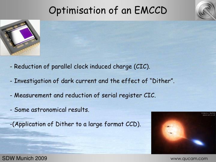
Optimisation of an EMCCD. Reduction of parallel clock induced charge (CIC). Investigation of dark current and the effect of “Dither”. Measurement and reduction of serial register CIC. Some astronomical results. (Application of Dither to a large format CCD). SDW Munich 2009.

E N D
Optimisation of an EMCCD • Reduction of parallel clock induced charge (CIC). • Investigation of dark current and the effect of “Dither”. • Measurement and reduction of serial register CIC. • Some astronomical results. • (Application of Dither to a large format CCD). SDW Munich 2009 www.qucam.com
Cuts through EMCCD bias frames Clock induced charge the dominant noise source. Optimisation process SDW Munich 2009 www.qucam.com
EMCCD primer Conventional part of register EM part of register FH2HV FH2DC FH2HV FH2DC FH1 FH1 FH1 FH2 FH2 FH1 FH3 FH3 FH3 FH3 t1 t2 t3 SDW Munich 2009 www.qucam.com
EMCCD primer 1056 columns CIC produced in all sections of the CCD. Image Area. Store Area. 16 elements 16 elements 604 elements 468 elements EM Amp. EM register Serial register Conventional Amp. Link section E2V CCD201 SDW Munich 2009 www.qucam.com
Multiplication noise Output of EM register in response to inputs between 1 and 5 e-. Note that an output signal of 400 e- could result from an input of either 4 or 5 e- with almost equal probability -> “Multiplication noise” SDW Munich 2009 www.qucam.com
Multiplication noise: Monte Carlo model Passage of 10 seperate photo-electrons are followed through the EM register. Overall EM gain=1000 Average SDW Munich 2009 www.qucam.com
Inverted Mode SDW Munich 2009 www.qucam.com
Inverted mode operation reduces dark current E2V CCD201, T=293K Holes are attracted from the channel stops. These then populate the surface of the CCD mopping up surface dark current. SDW Munich 2009 www.qucam.com
Inverted mode operation increases CIC -8V Electrode SiO2 P+ P+ n Channel stop Pixel charge packet p +4V P+ P+ n p Electron produced by impact ionisation During integration surface populated with holes that suppress surface dark current. During charge transfer when the pixel comes out of inversion the holes produce clock induced charge. SDW Munich 2009 www.qucam.com
Measuring parallel CIC in an FT CCD Transfer Readout Integration CCD201 Next frame integrating 1032 rows First row of parallel overscan will contain only 1038 rows of CIC. Image Store 1037 rows Last row of image will contain 2069 rows of CIC. So the parallel CIC should show a step in vertical cuts through bias frames that include a parallel overscan area. SDW Munich 2009 www.qucam.com
Non-inverted mode reduces parallel CIC Inverted operation Non-inverted operation CIC from 1032 row transfers Cuts through bias images that contain a parallel overscan. SDW Munich 2009 www.qucam.com
Summary Inverted Mode Non Inverted Mode Low Dark current Huge CIC High Dark current Low CIC SDW Munich 2009 www.qucam.com
But…..dark current non-linear with time! CCD201 data Non-inverted dark current suddenly drops by a factor of almost 100! CCD201 data SDW Munich 2009 www.qucam.com
Non-inverted dark current versus exposure time CCD201 data SDW Munich 2009 www.qucam.com
Non-Inverted mode conclusions -8V Electrode SiO2 P+ P+ n Channel stop Pixel charge packet p • Non inverted mode required for low parallel CIC. • For short exposures the corresponding increase in dark current is not seen. • Non-inverted mode operation preferred for EMCCDs The suppression of dark current could be explained by `Dither` (Jorden et al. `Secrets of E2V Technologies CCDs` SDW 2004). However, this explanation requires the presence of holes at the surface. The low CIC seems to indicate the very opposite (??). SDW Munich 2009 www.qucam.com
Measurement of serial-clock generated CIC Removed by DG operation The CCD201 contains a dump gate (DG) structure to assist in rapid clearing. It can also be used to measure serial generated CIC. CIC left behind by previous line readout CIC from current line readout Sum of the two SDW Munich 2009 www.qucam.com
Reduction of serial clock generated CIC Measurement of serial-clock generated CIC New image dimensions for purposes of test. Image Area. Store Area. EM Amp. EM register Serial register Link section DG Complete readout of pipeline for every row of image. SDW Munich 2009 SDW Munich 2009 www.qucam.com www.qucam.com
Reduction of serial-register CIC Reducing the serial high clock voltage from 10 to 8.5V reduced serial CIC . Lower voltages gave poor CTE. SDW Munich 2009 www.qucam.com
Final CIC levels Model used to find relative proportions of pre-EM-register and in-EM-register generated CIC events. Pre-reg = 0.02e- per pixel , In-reg = 0.011e- per pixel. Total 0.013e- per pixel. SDW Munich 2009 www.qucam.com
Dual-EMCCD spectroscopy system on William Herschel Telescope La Palma Red arm of ISIS spectrograph: CCD201 Blue arm : additional CCD201 SDW Munich 2009 www.qucam.com
CCD201 cryogenic EMCCD camera SDW Munich 2009 www.qucam.com
EMCCD spectroscopy: astronomical results Cataclysmic Variable: white dwarf and less massive donor orbiting around their common centre of gravity. Orbital periods from 5 minutes to > 12 hours. Most of the light is emitted from an accretion disc surrounding the white dwarf. SDSSJ1433 Artists impression, Mark Garlick Spectrographic observations show the double emission lines produced by the high velocity material orbiting within the accretion disc. SDW Munich 2009 www.qucam.com
Appearance of an EMCCD spectrum 0.22A per pixel dispersion. Mean intensity of continuum=0.08e-/s per wavelength step Exposure time=30s Target g´=18.5 Reference SDSSJ1433 SDW Munich 2009 www.qucam.com
EMCCD spectroscopy: astronomical results With an EMCCD we can use short exposures to obtain time resolved spectra of the accretion disc. It is then possible to measure the to-and-fro motion of the white dwarf and constrain the mass of the secondary star. Tulloch, Rodriguez-Gil, Dhillon, MNRAS 397, L82-86, 2009 Series of time resolved spectra Radial velocity of the white dwarf. SDW Munich 2009 www.qucam.com
EMCCD spectroscopy: astronomical results This type of time-resolved high-dispersion spectroscopy would have been impossible with a conventional detector. Actual EMCCD spectrum Model spectrum: 3e- read noise SDW Munich 2009 www.qucam.com
Aside: Dither clocking in a large format CCD 2k x 6k pixel frame-transfer CCD42C0. Conventional inverted mode operation Intended for Eddington. Now destined for Mercator telescope in La Palma High-speed photometry, short exposure time. Use of Peltier cooler. SDW Munich 2009 www.qucam.com
´Dither´ induced cosmetic defects FV2 FV3 FV1 “Wobble” sequence repeated at intervals ranging from 1ms to 4s at temperatures from 213 to 233K during exposure. +3V -9V Flat field SDW Munich 2009 www.qucam.com
Use of ´Dither´ with a CCD42CO Profile through 6 defects after 10,000 dither clock cycles. Charge is conserved, defect amplitude < 1e- / cycle. T=220K SDW Munich 2009 www.qucam.com
Use of ´Dither´ with a CCD42CO SDW Munich 2009 www.qucam.com
Use of ´Dither´ with a CCD42CO Approximately equal to an extra 10 degrees of cooling. SDW Munich 2009 www.qucam.com
Optimisation of an EMCCD End of presentation www.qucam.com SDW Munich 2009 www.qucam.com