Download
1 / 22
220 likes | 236 Views
This presentation focuses on assessing the sizing of air conditioning systems in buildings, taking into consideration the cooling requirements. It discusses the consequences of overdesigning or under-sizing the systems and provides guidance on improvements and alternatives. The presentation covers factors such as cooling loads, heat gains, design conditions, psychometrics, and cooling load diversities. Relevant literature, software, and estimation techniques are also mentioned.

E N D
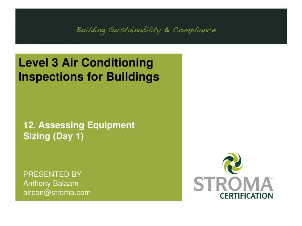
Level 3 Air Conditioning Inspections for Buildings 12. Assessing Equipment Sizing (Day 1) PRESENTED BY Anthony Balaam aircon@stroma.com
Size – Versus - Load Regulation 22 of EPB Regulations “The inspection report must include an assessment of the air-conditioning efficiency and the sizing of the system compared to the ‘cooling requirements’ of the building, and contain appropriate advice on possible improvements to the system, replacement of the system and any alternatives.”
Cooling Loads Overdesign and Over-sizing Creates:- 1. Environmentallyunacceptable 2. Operational at part load, generates reduced efficiency 3. Uneconomical 4. Overall wasteful Under-sizing Creates:- 1. Conditions required for thermal comfort will ‘not be met’.
Cooling Loads Ambient Design Temperatures 1. The selection of design ambient temperatures affects cooling duty; • These are obtained from established ‘weather data’ (summer time temperatures). 2. It is possible for cooling applications that:- temp°C determining the cooling load≠ temp°C sizing the cooling plant. E.g. a dry bulb temperature of 28°C may be used for cooling load calculations, but a temperature of 32°C taken for selecting air cooled plant condensing equipment. • Note:- overestimation of cooling load – enables operation at higher ambient (but the plant will be marginally oversized).
Heat Gains Heat Gains – Can Cycle From ‘Zero’to ‘100%’ The following contribute to the cooling load:- • 1. Heat flow through walls, floors, roofs, doors, glazing. • 2. Heat from air changes from doors, windows, ventilation systems. • 3. Heat from solar radiation. • 4. Heat from people within occupied zones. • 5. Heat from lighting and other energy consuming equipment. • 6. Heat from fans and pump motors associated with the systems. • (be aware of being paid for twice!)
Design conditions Architectural layouts and elevations Admittance Fresh air ventilation load (sensible and latent) Building use data Building air tightness Fabric details U-values Solar data Internal heat gain (sensible and latent) Infiltration heat gain (sensible and latent) Fabric heat gain (sensible) Solar heat gain (sensible) Duct/fan heat gains Total room heat gain (sensible and latent) Sensible/total room ratio Room cooling emitter size Psychometrics Dehumidification load Pipework distribution system design Distribution pipework heat gains Central Cooling Load Cooling load diversities MAXIMUM INSTANTANEOUS COOLING LOAD Chillers Selection Plant size ratio Cooling Design Detailed calculations to reasonable accuracy. Part L compliance (post 2002) will limitoversizing to 15-20%. Plant selection limitations cause oversizing.
Cooling Design Design Recommendation guidance Literature:- 1. CIBSE Guide A: Environmental Design 2. CIBSE TM37: Improved Design for Solar Shading Control 3. CIBSE TM46: Energy Benchmarks 4. BSRIA: Rules of Thumb - Guidelines for Building Services 5. BSRIA/CIBSE: A Practical Guide to HVAC Building Services Calculations 6. BSRIA/CIBSE: Illustrated Guide to Mechanical Building Services 7. CIP (central information point) database file (available from www.ndepcregister.com) Software:- 1. Hevacomp 2. IES 3. Design Builder 4. TAS
Cooling Estimation What is Required:- Estimate of current loads. Which provides:- An Indicationof whether the system is of appropriate size. An Indicationof the current state of the building andthe system. Does assists in:- Future maintenance, replacement or upgrading of the system.
Cooling Estimation It helps to inform on:- replacementbylike-for-like; or whether smaller more efficient system will suffice. It will indicate:- Specificand localised load issues Special cooling measures required Or identification of oversized plant • Remember - Wasteof energyiscostly.
Unitary or Packged Systems Rules of Thumb Guidance values:- For units up to7m from windows:- • 100W/m2 for up 25% glazing • 160W/m2 for up to 60% glazing For units beyond 7m from the windows (internal areas):- • 75W/m2 For larger areas (perimetersplus internal areas) • 110 W/m²for 30% glazing
Unitary or Packged Systems Rules of Thumb:- Estimation Only! Does not account for :- ‘orientation’, ‘windows details’, ‘shading details’ (whether external or internal), or ‘site details’ (adjacent buildings, trees etc.). Significant factors should be noted in your site notes.
Unitary/ Packaged Centralised Systems Design Guidance:- Literature:- CIBSE Guide A: Environmental Design CIBSE TM37: Improved Design for Solar Shading Control CIBSE TM46: Energy Benchmarks BSRIA: Rules of Thumb - Guidelines for Building Services BSRIA/CIBSE: A Practical Guide to HVAC Building Services Calculations BSRIA/CIBSE: Illustrated Guide to Mechanical Building Services CIP database file (available from www.ndepcregister.com) Software:- Hevacomp IES Design Builder TAS Population Density example:- 70 people in an office 800sq.m = 11.5sq.m per person Upper value 58w/sq.m Lower value 32w/sq.m Upper value lower value
10m Method 1 Example 1 1 - Internal Area (I) 1m 2 - Perimeter Area (P) Upper Heat Gain :-= 7,750W / 80m2 = 97 W/m2 8m Total Floor Area = 80m2 Glazing = <25% Method 1 :- Rule of thumb Using Rules of Thumb (CIBSE:TM44):- (I + P) 1 - Internal Area Heat Gain = 75W/m2 * (10m*1m) = 750W 2 - Perimeter Area Heat Gain = 100W/m2 * (7m*10m) = 7,000W Total Zone Heat Gain = 750W +7,000W = 7,750W = 7.75kW +20% Tolerance = 9.3kW Installed machine Capacity = 12.5kW Installed Capacity is deemed to bemore than expected (using rules of thumb)
Method 2 Example 2 10m 1 - Internal Area 1m 2 - Perimeter Area Upper Heat Gain :-= 8,800W / 80m2 = 110 W/m2 8m Total Floor Area = 80m2 Glazing = <30% Method 1 :- Rule of thumb Using Rules of Thumb (CIBSE:TM44):- (larger areas) 1 - Internal Area Heat Gain + Perimeter heat gain = 110W/m2 * (10m*8m) = 8,800W Total Zone Heat Gain = 8,800W = 8.80kW +20% Tolerance = 10.56kW Installed machine Capacity = 12.5kW Installed Capacity is deemed to bemore than expected (using the average rules of thumb)
Method 3 Example 3 10m 1 - Internal Area 1m 2 - Perimeter Area Method 3 :- CIBSE Rule of ‘occupation density’ Area = 8m * 10m = 80m² Density/m² = 80/12 = 6.7m²/p 8m Total Floor Area = 80m2 Glazing = <25% 12 people Occupants: 12No (Using CIBSE GUIDE A graph) Lower value = 43W/m² of floor space Upper value = 78W/m² LV = 80m² * 43W/m² = 3,440W UP = 80m² * 78W/m² = 6,240W Total Heat Gain range = 3,440W * (1+20%) = 4.128kW to 6,240W*(1+20%) =7.49kW Installed Capacity = 12.5kW Installed Capacity is more than expected
Method 4 Example 4 10m 1 - Internal Area 1m 2 - Perimeter Area Upper Heat Gain = 13,330W / 80m2 = 167 W/m2 8m Total Floor Area = 80m2 Glazing = <25% Method 4 :- CIBSE Rule of ‘occupation’ Occupants: 70No @ 115W per person (SITE SURVEY + CIBSE GUIDE A) Equipment: 1No Laptop @ 150W, 1No Projector @ 450W (SITE + CUIDE GUIDE A) Lighting: 22lamps@100W, 4@20W (SITE SURVEY) Solar:30W/m², pre2002 building ADL2B Occupants: 70 * 115W = 8,050W Equipment: 150W + 450W = 600W Lighting: (22*100W) + (4*20W) = 2,280W Solar: 30W/m2* 80m2 = 2,400W Total Heat Gain = 13,330W = 13.3kW +20% Tolerance = 16kW Installed Capacity = 12.5kW Installed Capacity is Less that of expected
10m Method 2 Example 2 1 - Internal Area 1m 2 - Perimeter Area Upper Heat Gain :-= 8,800W / 80m2 = 110 W/m2 8m Total Floor Area = 80m2 Glazing = <30% Revised Method 2 :- Rule of thumb Using Rules of Thumb (BSRIA 5th Edition from table = 87W/m²):- 1 - Internal Area Heat Gain + Perimeter heat gain = 87W/m2 * (10m*8m) = 6,960W Total Zone Heat Gain = 6,960W = 6.96kW +20% Tolerance = 8.352kW Installed machine Capacity = 12.5kW Installed Capacity is deemed to bemore than expected (using the average rules of thumb)
Reference Material “Heating, Ventilation, Air Conditioning and Refrigeration”, CIBSE Guide B, Chartered Institute of Building Services Engineers, 2005 “CIBSE KS13: Refrigeration”, CIBSE Knowledge Series, Chartered Institute of Building Services Engineers, 2008 “ASHRAE Handbook: Fundamentals”, American Society of Heating, Refrigeration and Air Conditioning Engineers, 2001 “BS EN 378: Specification for Refrigeration Systems and Heat Pumps; Part 1: 2000: Basic Requirements, Definitions, Classification and Selection Criteria; Part 2: 2000: Design, Construction, Testing, Marking, and Documentation; Part 3: 2000: Installation Site and Personal Protection; Part 4: 2000: Operation, Maintenance, Repair and Recovery”, London: British Standard Institution, 2000 “Non-Domestic Heating, Cooling, and Ventilation Compliance Guide”, Department For communities and local Government Building Regulations Approved Document L2B”, Department For communities and local Government “Inspection of Air Conditioning Systems”, CIBSE TM44:2007
LEVEL 3 Air ConditioningENERGY ASSESSORS TRAINING ANY QUESTIONS OR FEEDBACK ON ANY SLIDE
STROMA Certification Ltd – Contacts Web Links www.stroma.com/certification Contacts:- STROMA Certification Ltd. 4 Pioneer Way, Castleford, WF10 5QU 0845 621 11 11 training@stroma.com
End of this section Test 2 -. Package Systems Cooling Exercise – Question 1 a,b,c,d
20m Example 1 1 - Internal Area 4m Upper Heat Gain :-= 7,750W / 80m2 = 97 W/m2 10m Total Floor Area = 200m2 Glazing = <25% Method 1 Rule of thumb 2 - Perimeter Area Using Rules of Thumb (CIBSE:TM44):- 1 - Internal Area Heat Gain = 75W/m2 * (20m*4m) = 6,000W 2 - Perimeter Area Heat Gain = 100W/m2 * (6m*20m) = 12,000W Total Zone Heat Gain = 6,000W +12,000W = 18,000W = 18.00kW +20% Tolerance = 21.6kW Installed machine Capacity = 12.5kW Installed Capacity is deemed to beless than expected (using rules of thumb)