Download
1 / 13
130 likes | 283 Views
Digital Transceiver Implementation. Characterization Presentation Barak Shaashua Barak Straussman Supervisor: Idan Shmuel. Project Goals. Implementation of transceiver with Labview on FPGA . Project parts: 16 QAM Tranceiver 8 PSK Tranceiver. Transmitter Block Diagram. I.

E N D
Digital Transceiver Implementation Characterization Presentation Barak Shaashua Barak Straussman Supervisor: IdanShmuel
Project Goals • Implementation of transceiver with Labview on FPGA. • Project parts: • 16 QAM Tranceiver • 8 PSK Tranceiver
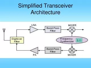
Transmitter Block Diagram I Source Coder Channel Coder Serial / Parallel Constellation Mapping Q LPF DAC I + π/2 ISI Filter Up Converter Combiner Q Sin(wt) DAC LPF
Receiver Block-Diagram LPF I Timing & Carrier Recovery + π/2 ADC RF Sin(wt) Q LPF I Channel Decoder Symbol Decision Constellation Mapping Parallel / Serial Q (+ Source)
Project Environment Software • LabView 2010 v.10 (FPGA, RF toolbox) • Tabor – ArbConnection Hardware • FPGA – Virtex5, NI FlexRio Board • NI 5761 Digitizer • Tabor – wx2182 • Scope, Spectrum Analyzer
Rates • FPGA – 400Mb/s • Tabor – 2.1GS/s, 16MB waveform memory • Digitizer – 250MS/s • GPIB – 1.5MB/s • LAN – Fast Ethernet 100Mb/s • Coaxial cable – BW 4.2Ghz • Our IF frequency: 100Mhz • Tabor Symbol Rate possible: 100Khz – 500Mhz
Channel Coder • Block Code – as Hamming Code: • Implementation with vectors and matrices representation • Able to detect up to 2 errors and correct one
ISI • Symbol interference results of dispersion in transmission medium • ISI filter decreases this interference • Filter: Root Raised Cosine
Constellation Mapping • Implementation with Lock Up Table • Symbols - according to Gray Code
Timing & Carrier Recovery • Recovers 3 elements: • Symbol Timing – Grander Algorithm • Carrier Frequency • Carrier Phase • Makes use of Digital PLL
Symbol Decision • Noise Sources: Channel, Quantization, Aliasing… • Assumptions: • Noise is AWGN, orthogonal & i.i.d • Uniform symbol probability • Symbols decision according to Euclidian distance only.