Download
1 / 63
640 likes | 662 Views
Chapter 3: Networking and Internetworking. Concepts Switching Routing (IP) End-to-End Protocols (UDP/TCP) Wireless LAN. Introduction. (a). (b). Building Blocks. Nodes: PC, special-purpose hardware… hosts switches Links: coax cable, optical fiber… point-to-point multiple access.

E N D
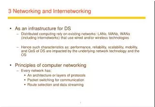
Chapter 3: Networking and Internetworking • Concepts • Switching • Routing (IP) • End-to-End Protocols (UDP/TCP) • Wireless LAN
(a) (b) Building Blocks • Nodes: PC, special-purpose hardware… • hosts • switches • Links: coax cable, optical fiber… • point-to-point • multiple access ■ ■ ■
Switched Networks • two or more nodes connected by a link, or • A network can be defined recursively as... • two or more networks connected by a node
router/ 138.37.95.240/29 138.37.95.241 Campus firewall subnet router hammer Staff subnet Student subnet 138.37.88.251 138.37.94.251 138.37.88 138.37.94 compute file server/ Eswitch Eswitch server gateway bruno 138.37.88.249 custard printers 138.37.94.246 dialup server % henry 138.37.88.230 other servers file server hotpoint 138.37.88.162 web server copper 138.37.88.248 hub hub desktop computers desktop computers 138.37.88.xx 138.37.94.xx sickle Campus 138.37.95.248/29 100 Mbps Ethernet router/ router subnet 138.37.95.249 firewall 1000 Mbps Ethernet Eswitch: Ethernet switch Simplified view of the QMW Computer Science network (in mid-2000)
Addressing and Routing • Address: byte-string that identifies a node • usually unique • Routing: process of forwarding messages to the destination node based on its address • Types of addresses • unicast: node-specific • broadcast: all nodes on the network • multicast: some subset of nodes on the network
Inter-Process Communication • Turn host-to-host connectivity into process-to-process communication. • Fill gap between what applications expect and what the underlying technology provides.
Multiplexing • Circuit switching: carry bit streams • original telephone network • Packet switching: store-and-forward messages • Internet
■ ■ ■ Statistical Multiplexing • On-demand time-division • Schedule link on a per-packet basis • Packets from different sources interleaved on link • Buffer packets that are contending for the link • Buffer (queue) overflow is called congestion
What Goes Wrong in the Network? • Bit-level errors (electrical interference) • Packet-level errors (congestion) • Link and node failures • Packets are delayed • Packets are deliver out-of-order • Third parties eavesdrop
Conceptual layering of protocol software Message received Message sent Layer n Layer 2 Layer 1 Communication Sender Recipient medium
Protocol layers in the ISO Open Systems Interconnection (OSI) model • most peer-to-peer communication is indirect • peer-to-peer is direct only at hardware level
Layer Description Examples Application Protocols that are designed to meet the communication requirements of FTP HTTP, , SMTP, specific applications, often defining the interface to a service. CORBA IIOP Presentation Protocols at this level transmit data in a network representation that is Secure Sockets independent of the representations used in individual computers, which may ( SSL),CORBA Data differ. Encryption is also performed in this layer, if required. Rep. Session At this level reliability and adaptation are performed, such as detection of failures and automatic recovery. Transport This is the lowest level at which messages (rather than packets) are handled. TCP, UDP Messages are addressed to communication ports attached to processes, Protocols in this layer may be connection-oriented or connectionless. Network Transfers data packets between computers in a specific network. In a WAN IP, ATM virtual or an internetwork this involves the generation of a route passing through circuits routers. In a single LAN no routing is required. Data link Responsible for transmission of packets between nodes that are directly Ethernet MAC, connected by a physical link. In a WAN transmission is between pairs of ATM cell transfer, routers or between routers and hosts. In a LAN it is between any pair of hosts. PPP Physical The circuits and hardware that drive the network. It transmits sequences of Ethernet base- band binary data by analogue signalling, using amplitude or frequency modulation signalling, ISDN of electrical signals (on cable circuits), light signals (on fibre optic circuits) or other electromagnetic signals (on radio and microwave circuits). OSI protocol summary
Message Layers Application Messages (UDP) or Streams (TCP) Transport UDP or TCP packets Internet IP datagrams Network interface Network-specific frames Underlying network TCP/IP layers
Application message port TCP header TCP IP header Ethernet header IP Ethernet frame Encapsulation in a message transmitted via TCP over an Ethernet
FTP HTTP SMTP TFTP UDP TCP IP NET NET NET ■ ■ ■ 1 2 n Internet Architecture • Hourglass Design • Application vs Application Protocol (FTP, HTTP)
Host Host Application Application Application Application program program program program Data Data RRP RRP RRP Data RRP Data HHP HHP HHP RRP Data Protocol Multiplexing • Multiplexing and Demultiplexing (demux key) • Encapsulation (header/body)
Scalable Networks • Switch • Connect links to form a larger network. • Connect switches to form a larger network. • forwards packets from input port to output port • port selected based on address in packet header • Advantages • store and forward • support large numbers of hosts
Datagram Switching • No connection setup phase • Sometimes called connectionless model • Each packet forwarded independently • Each switch maintains a forwarding (routing) table • Eg. Switch 1
Datagram Model • Source host has no way of knowing if the network is capable of delivering a packet or if the destination host is even up. • No QoS • Since packets are treated independently, it is possible to route around link and node failures. • Since every packet must carry the full address of the destination, the overhead per packet is higher than for the connection-oriented model.
Learning Bridges • Do not forward to all the other ports (broadcast) when unnecessary • Maintain forwarding table Host Port A 1 B 1 C 1 X 2 Y 2 Z 2 • Learn table entries based on source address • Table is an optimization; need not be complete • Always forward broadcast frames
Internetworking • Concatenation of Different Networks
IP Internet • Connecting Problem 1: Heterogeneity of Networks • Solution: Layered Protocol Stack (IP over …… ) • Problem 2: Scalability in Routing and Addressing • Solution: Address Hierarchy
Service Model • Connectionless (datagram-based) • Best-effort delivery (unreliable service) • packets can be lost, delayed, duplicated, delivered out of order. • Datagram format: IP header
IP Header • Version (always set to the value 4 for IP v4) • IP Header Length (number of 32 -bit words forming the header, usually five) • Size of Datagram (in bytes, header + data) • Flags 3 bits: R (reserved bit set to 0) DF (Don't fragment ) MF (More fragments) • Time To Live (Number of hops /links which the packet may be routed over, decremented by most routers - used to prevent accidental routing loops) • Protocol (the type of transport packet being carried (e.g. 1 = ICMP; 6 = TCP; 17= UDP). • Header Checksum (A 1's complement checksum of IP header, updated whenever the packet header is modified by a node. Packets with an invalid checksum are discarded by all nodes in an IP network) • Source Address / Destination Address
Internet address structure, showing field sizes in bits globally unique hierarchical: network + host
Decimal representation of Internet addresses octet 1 octet 2 octet 3 Range of addresses Network ID Host ID 1.0.0.0 to Class A: 1 to 127 0 to 255 0 to 255 0 to 255 127.255.255.255 Network ID Host ID 128.0.0.0 to Class B: 128 to 191 0 to 255 0 to 255 0 to 255 191.255.255.255 Network ID Host ID 192.0.0.0 to Class C: 0 to 255 0 to 255 1 to 254 192 to 223 223.255.255.255 Multicast address Multicast address 224.0.0.0 to Class D (multicast): 224 to 239 0 to 255 0 to 255 1 to 254 239.255.255.255 240.0.0.0 to Class E (reserved): 240 to 255 0 to 255 0 to 255 1 to 254 255.255.255.255
Datagram Forwarding Strategy • Every datagram contains destination’s address • if connected to destination network, then forward to the host in LAN • If network number of destination IP == my network number • if not directly connected, then forward to the host’s default router • Each router maintains a forwarding table • forwarding table maps network number (rather than host address) into next hop or interface number (if directly connected)
Traffic: H1 → H3, H1 → H8 R1: default router is R2 R2 Routing Table: Network Number Next Hop Interface 1 R3 interface 1 2 R1 interface 0 3 - interface 1 4 - interface 0
Address Translation in LAN • Map IP addresses into physical addresses of the destination host (if connected directly) or the next hop router • ARP • Each host caches its table of IP to physical address bindings • table entries are discarded if not refreshed • timeout in about 10 minutes • broadcast request if IP address not in table • target machine send its physical address to the sender • target machine also updates add entry of the source in its table • It is likely that the target will send IP packets to the source later on. • Other hosts (who receives the broadcasted request) update table if already have an entry
End-to-End Protocols • Underlying best-effort network • drop messages • re-orders messages • delivers duplicate copies of a given message • limits packet (not message) to some finite size • delivers messages after an arbitrarily long delay • Common end-to-end services • guarantee message delivery • deliver messages in the same order they are sent • deliver at most one copy of each message • support arbitrarily large messages • support synchronization between sender and receiver • allow the receiver to flow control the sender • support multiple application processes on each host
End-to-End Protocols (UDP/TCP)
Simple Demultiplexor (UDP) • Unreliable and unordered datagram service • Adds multiplexing • No flow control or error control • no need for sender-side buffer) • Endpoints identified by ports • servers listens at well-known ports! • see /etc/services on Unix • Header format • Optional checksum • psuedo header (IP.src, IP.dsest, IP.proto, UDP.len) + UDP header + data
Application process Application process Write Read bytes bytes TCP TCP Send buffer Receive buffer ■ ■ ■ Segment Segment Segment Transmit segments TCP Overview • Connection-oriented • Byte-stream • app writes bytes • TCP sends segments • app reads bytes • Full duplex • Flow control: keep sender from overrunning receiver • Congestion control: keep sender from overrunning network
Segment Format (cont) • Each connection identified with 4-tuple: • (SrcPort, SrcIPAddr, DsrPort, DstIPAddr) • Sliding window + flow control • acknowledgment, SequenceNum, AdvertisedWinow • Flags • SYN, FIN, RESET, PUSH, URG, ACK • Checksum • pseudo header + TCP header + data
Connection Establishment and Three-Way Handshake Active participant Passive participant (client) (server) SYN, SequenceNum = x SYN+ACK, SequenceNum=y, Acknowledgment =x+1 ACK, Acknowledgment =y+1
Reliability and Flow Control • The receiver’s buffer has two purposes • Reorder segments received out of order • Hold data unread by the application • The sender cannot send more than AdvertisedWindow bytes of unacknowledged data at any given time (Flow Control). • The sender retransmits after timeout • Adaptive RTT measurement.
Socket API • Creating a socket int socket(int domain, int type, int protocol) • type = SOCK_STREAM, SOCK_DGRAM, SOCK_RAW • Passive Open (on server) int bind(int socket, struct sockaddr *addr, int addr_len) int listen(int socket, int backlog) int accept(int socket, struct sockaddr *addr, int addr_len) • Active Open (on client) int connect(int socket, struct sockaddr *addr, int addr_len) • Sending/Receiving Messages int send(int socket, char *msg, int mlen, int flags) int recv(int socket, char *buf, int blen, int flags)
Ethernet Overview • The most successful Local Area Networks • Bandwidth: 10Mbps, 100Mbps (Fast), 1Gbps • Avoid Simultaneous on a Shared Line: CSMA/CD • multiple access • carrier sense: • listen before transmitting. • distinguish an idle and busy link. • collision detection • listen while transmitting. • Collision: What you hear is different from what you listen
Ethernet Frame • Frame Format • Addresses • unique, 48-bit unicast address assigned to each adapter • example: 8:0:e4:b1:2 • Every body hears the frame (shared media). But the one with matching destination address picks up. • broadcast: all 1s • multicast: first bit is 1. The host can configure its adaptor to accept some multicast addresses • Preamble (a seq. alternating 0s and 1s ) indicates the start of a frame • Type: high-level protocols
Transmit Algorithm • If line is idle… • send immediately • upper bound message size of 1500 bytes • Limited occupancy on the line. • must wait 9.6us between back-to-back frames • To allow other hosts to send. • If line is busy… • wait until idle and transmit immediately
Collisions • The remote side may send its frame before it hears the frame currently being sent • Both sides detect an idle line • Due to the propagation delay • For A to detect the collision • Collisions can only be detected during transmission • 51.2us •10Mbps = 64 bytes