Download
1 / 34
340 likes | 368 Views
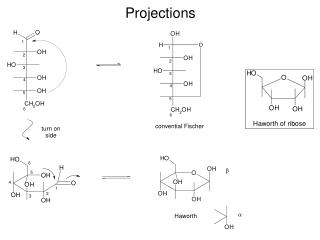
Projections of Line. NOTATIONS. FOLLOWING NOTATIONS SHOULD BE FOLLOWED WHILE NAMEING DIFFERENT VIEWS IN ORTHOGRAPHIC PROJECTIONS. OBJECT POINT A LINE AB. IT’S TOP VIEW a a b. IT’S FRONT VIEW a’ a’ b’.

E N D
NOTATIONS FOLLOWING NOTATIONS SHOULD BE FOLLOWED WHILE NAMEING DIFFERENT VIEWS IN ORTHOGRAPHIC PROJECTIONS. OBJECT POINT A LINE AB IT’S TOP VIEW a a b IT’S FRONT VIEWa’a’ b’ IT’S SIDE VIEW a” a” b”
THIS QUADRANT PATTERN, IF OBSERVED ALONG X-Y LINE ( IN RED ARROW DIRECTION) WILL EXACTLY APPEAR AS SHOWN ON RIGHT SIDE AND HENCE, IT IS FURTHER USED TO UNDERSTAND ILLUSTRATION PROPERLLY. 2nd Quadrant VP 1ST Quad. 2nd Quad. F.V. 1st Quadrant Y Observer HP X Y X 3rdQuadrant Observer 4th Quad. 3rd Quad. 4th Quadrant
VP VP OBSERVER OBSERVER OBSERVER OBSERVER HP HP HP HP VP VP POINT A IN 1ST QUADRANT POINT A IN 2ND QUADRANT 15 a’ 15 A B b’ 15 b 20 a c 15 20 d c’ C d’ POINT A IN 4TH QUADRANT POINT A IN 3RD QUADRANT 15 D 15 Convention: Horizontal plane is always rotated clockwise
For Tv For Tv For Tv POINT A IN HP & INFRONT OF VP POINT A ABOVE HP & IN VP POINT A ABOVE HP & INFRONT OF VP Y Y For Fv For Fv For Fv X X ORTHOGRAPHIC PRESENTATIONS OF ALL ABOVE CASES. a’ VP VP VP a’ a a’ X Y X Y a X Y a HP HP HP PROJECTIONS OF A POINT IN FIRST QUADRANT. A a’ a’ A Y a’ a a X A a Fv above xy, Tv below xy. Fv above xy, Tv on xy. Fv on xy, Tv below xy.
Projection of lines, planes, solids • Line – consists of 2 points • Plane – consists of 3 or more points • Solid – consists of more than 3 points Therefore in order to project lines, planes and solids, we need to project their corresponding points and join them
PROJECTIONS OF STRAIGHT LINES. AIM:- TO DRAW IT’S PROJECTIONS - FV & TV. INFORMATION REGARDING A LINE: IT’S LENGTH, POSITION OF IT’S ENDS WITH HP & VP IT’S INCLINATIONS WITH HP & VP SIMPLE CASES OF THE LINE • A VERTICAL LINE ( LINE PERPENDICULAR TO HP & // TO VP) • LINE PARALLEL TO BOTH HP & VP. • LINE INCLINED TO HP & PARALLEL TO VP. • LINE INCLINED TO VP & PARALLEL TO HP. • LINE INCLINED TO BOTH HP & VP.
Orthographic Pattern (Pictorial Presentation) V.P. Note: Fv is a vertical line Showing True Length & Tv is a point. a’ a’ V.P. b’ Fv A V.P. B b’ a’ Y A b’ X Y Y B Tv a b X X H.P. (Pictorial Presentation) V.P. Note: Fv & Tv both are // to xy & both show T. L. Fv a’ b’ b a X Y a b Tv H.P. For Tv 1. FV A Line perpendicular to Hp & // to Vp For Fv a b TV Orthographic Pattern For Tv 2. A Line // to Hp & // to Vp F.V. For Fv T.V.
V.P. Fv inclined to xy Tv parallel to xy. b’ F.V. a’ X Y a b T.V. b’ V.P. a’ V.P. H.P. b’ B F.V. B A Tv inclined to xy Fv parallel to xy. V.P. Y a’ Fv a’ b’ b A a b Ø T.V. X a X Y a Ø Tv b H.P. True Length 3. A Line inclined to Hp and parallel to Vp (Pictorial presentation) Orthographic Projections 4. F.V. A Line inclined to Vp and parallel to Hp (Pictorial presentation) Ø T.V. True Length
V.P. b’ FV a’ On removal of object i.e. Line AB Fv as a image on Vp. Tv as a image on Hp, For Tv For Tv X Y b’ b’ V.P. V.P. a B B F.V. F.V. TV Y Y H.P. a’ a’ b For Fv For Fv A A X X a a b b T.V. T.V. Orthographic Projections Fv is seen on Vp clearly. To see Tv clearly, HP is rotated 900 downwards, Hence it comes below xy. Note These Facts:- Both Fv & Tv are inclined to xy. (No view is parallel to xy) Both Fv & Tv are reduced lengths. (No view shows True Length) 5. A Line inclined to both Hp and Vp (Pictorial presentation) NOTE: aand b are NOT the true angles (inclinations) of the line with the planes
Angles to be remember θ – Angle of inclination of actual line with HP Ø– Angle of inclination of actual line with VP α - Angle made by FV of line with HP Β – Angle made by TV of line with VP
Illustration No. 1 The FV of line AB measures 45 mm and apparent inclination with HP is 50º. The TV is 35 mm long. Complete the projection of the line AB. The point A is 10 mm above HP and 25 mm in front of VP.
Illustration No. 2 A line CD, 90 mm long, measures 72 mm in FV and 65 mm in TV. Draw the two views of the line if it fully lies in first quadrant. Find the inclination of line CD, if point C is 10 mm above HP and 15 mm in front of VP.
Illustration no. 3 A line BC 80 mm long is inclined at 45º to HP and 30º to the VP. Its end B is in the HP and 40 mm in front of VP. Draw the projections.
Illustration No. 4 Draw front view and Top view of line RS if the line is at 45º inclined with VP, 30º with HP. Given, point R is 20mm in front of VP, 25 mm above HP; point S is 55 mm in front of VP and 50 mm above HP.
Projections two lines Shortest distance between two lines • Two lines may be parallel, or intersecting, or non-parallel and non-intersecting. • When the lines are intersecting, the point of intersection lies on both the lines and hence these lines have no shortest distance between them. • Non-parallel and non-intersecting lines are called Skew Lines. • The parallel lines and the skew lines have a shortest distance between them. • The shortest distance between the two lines is the shortest perpendicular drawn between the two lines. • To draw perpendicular , one of the line should be point view and pt. view is drawn from true length. • Or to draw perpendicular from a pt. to line, the line should be true.
Shortest distance between two parallel lines • The shortest distance between two parallel lines is equal to the length of the perpendicular drawn between them. • If its true length is to be measured, then the two given parallel lines should be shown in their point views. • If the point views of the lines are required, then first they have to be shown in their true lengths in one of the orthographic views. • If none of the orthographic views show the given lines in their true lengths, an auxiliary plane parallel to the two given lines should be set up to project them in their true lengths on it. • Even the auxiliary view which shows the lines in their true lengths may not show the perpendicular distance between them in true length. Hence another auxiliary plane perpendicular to the two given lines should be set up. • Then the lines appear as points on this auxiliary plane and the distance between these point views will be the shortest distance between them.
Illustration no. 1 Complete the projections of line MN perpendicular to AB. The pt. N lies on AB. Determine TL of MN. If A(10, 30, 50), B(80,10,85), M(50, 30, 65).
Illustration no. 2 Find the shortest distance between line MN and Q. M(20,20,110), N(70,50,70), Q(50,20,110).
Find the angle between Two Intersecting Line
Illustration no. 1 Find the angle between two intersecting lines AB and CD, if A(30,30,60), B(70,45,80), C(20,40,80) and D(65, 30, y2).
Illustration no. 2 Determine the angle of intersection between AB and CD. If A(10, 40, 50), B(60, 20, 75), C(25, 20, 70), D(55, y1, 60).
Illustration no. 3 Find the angle between EF and FG if E(15, 10, 55), G(75, 40, 90), and F(40, 40, 50)
Projections of Parallel lines
Illustration no. 1 AB and CD are parallel to each other. Complete the projections of line AB, if it is 25 mm away from CD. Length of AB= 35 mm A(30, 10, z), C(15, 25, 55), D(55, 45, 75)
Illustration no. 2 Line makes 30º with FRP and its TL is 30mm. It is parallel to AB and 15 mm away from it. Draw the projections of CD if A(10, 50, 65), B(60, y1, 80), C(20, y1, 80).
Illustration no.1 Find the shortest distance between AB and CD lines if A(10, 45, 70), B(50, 45, 100), C(10, 10, 75), and D(50, 60, 75).