Download
1 / 54
570 likes | 998 Views
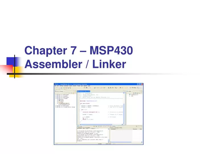
Chapter 7 – MSP430 Assembler / Linker. Concepts to Learn…. MSP430 Assembler High Level vs. Assembly Assembly Code Assembly Process MSP430 Assembler Assembly Directives Assembly Sections Linker Libraries Code Composer Essentials/Studio Systematic Decomposition Device: LED’s.

E N D
Concepts to Learn… • MSP430 Assembler • High Level vs. Assembly • Assembly Code • Assembly Process • MSP430 Assembler • Assembly Directives • Assembly Sections • Linker • Libraries • Code Composer Essentials/Studio • Systematic Decomposition • Device: LED’s Chapter 7 - MSP430 Assembler
Moving Up Levels of Abstraction Problems Algorithms Language Assembly code Machine (ISA) Architecture Machine code Micro-architecture LC-3 Architecture Circuits Logic gates, multiplexers, memory, etc. Devices Transistors Chapter 7 - MSP430 Assembler
Assembler Assembler An assembler outputs an object file as input to a linker program An assembler translates a program into machine code An assembly program is a text file Chapter 7 - MSP430 Assembler
High Level vs. Assembly High Level Languages More programmer friendly More ISA independent Each high-level statement translates to several instructions in the ISA of the computer Assembly Languages Lower level, closer to ISA Very ISA-dependent Each instruction specifies a single ISA instruction Makes low level programming more user friendly More efficient code High Level vs. Assembly Chapter 7 - MSP430 Assembler
Why Assembly Code? Allows us to work at a slightly higher level than machine language. Allows us to use symbolic names for opcodes Allows us to use symbolic names for memory locations - SUM, PRODUCT Don’t need to know every address of every storage location. Calculates addresses for us – really a big deal! Helps to allocate memory locations. Provides additional error checking High Level vs. Assembly Chapter 7 - MSP430 Assembler
Assembly Code Example Assembly Code ;******************************************************************************* ; CS/ECEn 124 Lab 4 - morse.asm: Student Code ;******************************************************************************* .cdecls C,LIST, "msp430x22x4.h“ ; include C header COUNT .equ 2000 ;------------------------------------------------------------------------------ .data ; data .bss cnt,2 ; ISR counter ;------------------------------------------------------------------------------ .text ; Program reset RESET: mov.w #0x0280,SP ; Initialize stack pointer mov.w #WDT_MDLY_0_5,&WDTCTL ; Set Watchdog interval to ~0.5ms mov.b #WDTIE,&IE1 ; Enable WDT interrupt bis.b #0x01,&P1DIR ; P1.0 output bis.b #0x20,&P4DIR ; P4.0 output mov.w #COUNT,&cnt ; initialize counter bis.w #LPM0+GIE,SR ; Enter LPM0 w/ interrupt jmp $ ; Loop forever; interrupts do all ; Watchdog Timer interrupt service routine ; WDT_ISR: xor.b #0x20,&P4OUT ; pulse buzzer dec.w &cnt ; decrement counter jne WDT_exit mov.w #COUNT,&cnt ; initialize counter xor.b #0x01,&P1OUT ; toggle P1.0 WDT_exit: reti ; return from interrupt .sect ".int10" ; MSP430 RESET Vector .word WDT_ISR ; Watchdog ISR .sect ".reset" ; MSP430 RESET Vector .word RESET ; Power Up ISR .end Instructions Labels Comments Directives Chapter 7 - MSP430 Assembler
Assembly Syntax The MSP430 assembler reads up to 200 characters per line. Any characters beyond 200 are truncated. Follow these guidelines: All statements must begin with a label, a blank, an asterisk, or a semicolon Labels are optional; if used, they must begin in column 1 One or more blanks must separate each field. Tab and space characters are blanks. Comments are optional. Comments that begin in column 1 can begin with an asterisk or a semicolon (* or ;), but comments that begin in any other column must begin with a semicolon. A mnemonic cannot begin in column 1 or it will be interpreted as a label Assembly Code [label[:]]mnemonic [operand list][;comment] Chapter 7 - MSP430 Assembler
Assembly Syntax Label Field Labels are optional for all assembly language instructions and for most (but not all) assembler directives When used, a label must begin in column 1 A label can contain up to 128 alphanumeric characters (A-Z, a-z, 0-9, _, and $) Labels are case sensitive and the first character cannot be a number A label can be followed by a colon (:). (If you do not use a label, the first character position must contain a blank, a semicolon, or an asterisk) The value of a label is the current value of the Location Counter A label on a line by itself is a valid statement If you do not use a label, the character in column 1 must be a blank, an asterisk, or a semicolon Assembly Code Chapter 7 - MSP430 Assembler
Assembly Syntax Mnemonic Field The mnemonic field follows the label field. The mnemonic field cannot start in column 1; if it does, it is interpreted as a label. The mnemonic field can begin with one of the following items: Machine-instruction mnemonic (such as ADD, MOV, JMP) Assembler directive (such as .data, .list, .equ) Macro directive (such as .macro, .var, .mexit) Macro call Assembly Code Chapter 7 - MSP430 Assembler
Assembly Syntax Operand Field The operand field follows the mnemonic field and contains one or more operands. The operand field is not required for all instructions or directives. An operand consists of the following items: Symbols Constants Expressions (combination of constants and symbols) You must separate operands with commas You use immediate values as operands primarily with instructions Use the # prefix to define an immediate value Assembly Code Chapter 7 - MSP430 Assembler
Assembly Syntax Constants The assembler maintains constants internally as a 32-bit quantities Constants are not sign extended (ie, 00FFh is equal to 00FF (base 16) or 255 (base 10); however, it does not equal -1 unless a byte directive) Types of constants: Decimal: string of decimal digits ranging from (-2147483648 to 4294967295 (ie, 1000, -32768) Hexadecimal: string of up to 8 hexadecimal digits followed by suffix ‘H’ (or ‘h’) or preceded by ‘0x’ (ie, 78h, 0x78) Binary: string of upt to 32 binary digits followed by suffix B (or b) (ie. 0000b, 11110000B) Assembly Code Chapter 7 - MSP430 Assembler
Assembly Syntax Expressions An expression is a constant, a symbol, or a series of constants and symbols separated by arithmetic operators. The 32-bit ranges of valid expression values are -2147 483 648 to 2147 483 647 for signed values, and 0 to 4 294 967 295 for unsigned values. Three main factors influence the order of expression evaluation: Parentheses Expressions enclosed in parentheses are always evaluated first. (You cannot substitute braces ( { } ) or brackets ( [ ] ) for parentheses) 8 / (4 / 2) = 4, but 8 / 4 / 2 = 1 Precedence groups Operators: when parentheses do not determine the order of expression evaluation, the highest precedence operation is evaluated first. 8 + 4 / 2 = 10 (4 / 2 is evaluated first) Left-to-right evaluation: when parentheses and precedence groups do not determine the order of expression evaluation, the expressions are evaluated from left to right Assembly Code Chapter 7 - MSP430 Assembler
Assembly Syntax Operators can be used in expressions and are evaluated according to precedence group Assembly Code GroupOperatorDescription 1 +, -, ~, ! Unary plus, minus, 1’s complement, Logical NOT 2 *, /, % Multiplication, Division, Modulo 3 +, - Addition, Subtraction 4 <<, >> Shift left, Shift right 5 <, <=, >, >= Less than, Less than or equal to, Greater than, Greater than or equal to 6 =[=], != Equal to, Not equal to 7 & Bitwise AND 8 ^ Bitwise exclusive OR (XOR) 9 | Bitwise OR Chapter 7 - MSP430 Assembler
Assembler Directives Assembly directives are used to specify: Starting addresses for programs Starting values for memory locations Specify the end of program text. ;******************************************************************************* ; CS/ECEn 124 Example Code ;******************************************************************************* .cdecls C,LIST, "msp430x22x4.h“ ; include C header COUNT .equ 2000 ;------------------------------------------------------------------------------ .data ; data .bss cnt,2 ; ISR counter ;------------------------------------------------------------------------------ .text ; Program reset RESET: mov.w #0x0280,SP ; Initialize stack pointer mov.w #WDT_MDLY_0_5,&WDTCTL ; Set Watchdog interval to ~0.5ms bis.w #LPM0+GIE,SR ; Enter LPM0 w/ interrupt jmp $ ; Loop forever; interrupts do all .sect ".reset" ; MSP430 RESET Vector .word RESET ; Power Up ISR .end Directives Assembly Code Chapter 7 - MSP430 Assembler
Assembly Process The assembler translates assembly language programs (.asm) into the machine language of the ISA (.obj). There is a 1-to-1 correspondence between assembly language instructions and instructions in the final machine language. First Pass: find all labels and their corresponding addressesthis information is stored in the symbol table Second Pass: convert instructions to machine language, using information from symbol table Assembly Process Chapter 7 - MSP430 Assembler
1st Pass: Construct Symbol Table Find the .text statement, which tells us the address of the first instruction Initialize location counter (LC) Incremented for each new instruction For each non-empty line in the program: If line contains a label, add label and LC to symbol table. Increment LC (according to instruction length.) 1. All instructions are 1, 2, or 3 words in length 2. Some directives like .bss or .string increment LC by the size of the operand. Stop when .end statement is reached. Assembly Process Chapter 7 - MSP430 Assembler
2nd Pass: Generate Machine Language Reset location counter (LC) For each executable assembly language statement, generate the corresponding machine language instruction. resolve labels referenced in instructions using the symbol table increment LC for each instruction as on pass 1 output resulting machine code to output files Stop when .end statement is reached. Assembly Process Chapter 7 - MSP430 Assembler
Assembly Style Guidelines Provide a program header, with author’s name, date, etc.,and purpose of program. Start labels, opcode, operands, and comments in same column for each line. (Unless entire line is a comment.) Use comments to explain what each register does. Remember, the assembler is case sensitive. Use meaningful symbolic names. Mixed upper and lower case for readability. ASCIItoBinary, InputRoutine, SaveR1 Provide comments between program sections. Each line must fit on the page -- no wraparound or truncations. Long statements split in aesthetically pleasing manner. Assembly Process Chapter 7 - MSP430 Assembler
MSP430 Assembler The MSP430 assembler translates your source code into machine language Source files may contain the following elements: Assembly directives Macro directives Assembly language instructions For more detailed information on each element, please refer to the MSP430 Assembly Language Tools User’s Guide (slau131b.pdf) Some of the most relevant aspects of the assembly language for the MSP430 will now be introduced MSP430 Assembler Chapter 7 - MSP430 Assembler
Stoplight Example MSP430 Assembler ;******************************************************************************* ; CS/ECEn 124 Lab 4 - stoplight.asm: Software Toggle P1.0 ;******************************************************************************* .cdecls C,LIST, "msp430x22x4.h" ; MSP430F2274 ;------------------------------------------------------------------------------ .text ; beginning of executable code ;------------------------------------------------------------------------------ RESET: mov.w #0x0280,SP ; init stack pointer mov.w #WDTPW+WDTHOLD,&WDTCTL ; stop WDT bis.b #0x01,&P1DIR ; set P1.0 as output mainloop: xor.b #0x01,&P1OUT ; toggle P1.0 mov.w #0,r15 ; use R15 as delay counter delayloop: dec.w r15 ; delay over? jnz delayloop ; n jmp mainloop ; y, toggle led ;------------------------------------------------------------------------------ ; Interrupt Vectors ;------------------------------------------------------------------------------ .sect ".reset" ; MSP430 RESET Vector .short RESET ; start address .end Chapter 7 - MSP430 Assembler
MSP430 Assembler The assembly programming tool processes the source code, producing an object file, and a descriptive listing of the entire process This process is completely controlled by macros, allowing conditional execution The MPS430 source code programs contains sequences of statements that have: Assembly directives Assembly instructions Macros, and Comments. MSP430 Assembler Chapter 7 - MSP430 Assembler
Assembler Syntax A line can have four fields label, mnemonic, operand list, and comment The general syntax is: {label[:]} mnemonic {operand list} {;comment} Some line examples are: .sect ".sysmem“ ; Data Space var1 .word 2 ; variable var1 declaration .text ; Program Space Label1: mov r4,r5 ; move R4 contents to R5 .end MSP430 Assembler Chapter 7 - MSP430 Assembler
Coding Guidelines The general coding guidelines: All statements must begin with a label, a blank, an asterisk, or a semicolon Labels are optional. If used, they must begin in column 1 One or more blanks or tabs must separate each field Comments are optional Comments that begin in column 1 can begin with an asterisk or a semicolon (* or ;), but comments that begin in any other column must begin with a semicolon A mnemonic cannot begin in column 1 or it will be interpreted as a label. MSP430 Assembler Chapter 7 - MSP430 Assembler
Constants The assembler supports several formats for constants: Binary integer: 11110000b 0xf0 Octal integer: 226q 0x96 Decimal integer: 25 0x19 Hexadecimal integer: 078h 0x78 Character: a 'a' Assembly time: value1 value1 .set 3 MSP430 Assembler Chapter 7 - MSP430 Assembler
Symbols Symbols are used as labels, constants, and substitution symbols A symbol name is a string of up to 200 alphanumeric characters (A-Z, a-z, 0-9, $, and _) A symbol cannot contain embedded blanks and the first character cannot be a number Symbols are case sensitive Symbols used as labels become symbolic addresses that are associated with locations in the program Labels used locally within a file must be unique. MSP430 Assembler Chapter 7 - MSP430 Assembler
Assembler directives supply data to the program and control the assembly process Assembler directives enable you to: Assemble code and data into specified sections Reserve space in memory for uninitialized variables Control the appearance of listings Initialize memory Assemble conditional blocks Define global variables Specify libraries from which the assembler can obtain macros Examine symbolic debugging information. Assembly Directives Assembler Directives Chapter 7 - MSP430 Assembler
Section Assembler Directives Assembler directives that define sections: Assembler Directives Chapter 7 - MSP430 Assembler
Assembler Directives Assembler directives that initialize constants (data and memory): Assembler Directives Chapter 7 - MSP430 Assembler
Assembler Directives Assembler directives that perform alignment and reserve space: Assembler Directives Chapter 7 - MSP430 Assembler
Assembler Directives Assembler directives that format the output listing: Assembler Directives Chapter 7 - MSP430 Assembler
Assembly List File A line in a listing file has four fields: Field 1: contains the source code line counter Field 2: contains the section program counter Field 3: contains the object code Field 4: contains the original source statement. Assembler Directives Chapter 7 - MSP430 Assembler
Assembler Directives Assembler directives that reference other files: Assembler Directives Chapter 7 - MSP430 Assembler
Assembler Directives Assembler directives that enable conditional assembly: Assembler Directives Chapter 7 - MSP430 Assembler
Assembler Directives Assembler directives that define structures: Directives that define symbols at assembly time: Assembler Directives Chapter 7 - MSP430 Assembler
Assembler Directives Assembler directives that perform miscellaneous functions: Assembler Directives Chapter 7 - MSP430 Assembler
Assembler Sections The smallest unit of an object file is called a section A section is a block of code or data that occupies contiguous space in the memory map Each section of an object file is separate and distinct. Object files contain three default sections: .text section contains executable code .data section contains initialized data .bss section reserves space for uninitialized variables. Assembler Sections Chapter 7 - MSP430 Assembler
Linker Example: process of linking two files together: Linker Chapter 7 - MSP430 Assembler
Library Routines Library A set of routines for a specific domain application. Example: math, graphics, GUI, etc. Defined outside a program. Library routine invocation Labels for the routines are defined as .def Each library routine contains its own symbol table. A linker resolves the external addresses before creating the executable image. Libraries Chapter 7 - MSP430 Assembler
Linking multiple files Libraries Chapter 7 - MSP430 Assembler
Code Composer Based on Eclipse framework Open source enabling rapid innovation Allows integration with other compilers, plugins One stop shop with TI MSP430 + FET Programmer + CCE Support Direct from TI Eclipse Community Third Parties Low cost solution (Free!) Code Composer Chapter 7 - MSP430 Assembler
CCE Window – C/C++ Perspective Code Composer Independent debugging and Programming view 1-click project debug • Project View • List of all Projects • Project Outline • Shortcut to all parts of the project • Code Window • Real-time breakpoints • Syntax highlighting • Problems View • Information • Warnings • Errors Console Build information Chapter 7 - MSP430 Assembler
CCE Window – Debug Perspective Code Composer Independent debugging and Programming view 1-click project debug • Target control • Start, stop, halt • Single stepping • Stack trace • Real-time, in-system MSP430 information • Register access • Flash, RAM, Info segment access • Disassembly view • Code Window • Real-time breakpoints • Syntax highlighting • Highly configurablewindow layout • User preferences • Plugin support Easy to viewprogram size info CPU Cycle counter Chapter 7 - MSP430 Assembler
The MSP430 Assembler To create a new Assembly language project: In File -> New Project choose Managed Make C/ASM Project(Recommended) Assign a name to the project in Project Name, (e.g., stoplight) Choose Project Type: MSP430 Executable In Additional Project Setting, do not choose any connection with other projects In the Device Selection page, select the target device MSPF2013 or MSP430F2274 Select configuration option: Assembly only Project At the end of this sequence of operations, a project named stoplight is opened in the work environment Code Composer Chapter 7 - MSP430 Assembler
The MSP430 Assembler Assembly project (continued): Assign a new source code file to the project. In the option Menu > File > Source File and create a new file called stoplight.asm In the project properties menu, set the entry point as identified by the label start This option is found on page Build C/C++ build > MSP430 Linker V3.0 > Symbol Management > Specify the program entry point for the output model (-entry point). Code Composer Chapter 7 - MSP430 Assembler
The MSP430 Assembly Listing To generate an assembly listing: Project -> Properties C/C++ Build -> Tool Settings -> MSP430 Compiler v3.x Assembler Options: Check Generate listing file (--asm_listing) To define program entry point: Project -> Properties C/C++ Build -> Tool Settings -> MSP430 Linker v3.x Symbol Management: Specify the program entry point for the output model (-- entry point) Enter the start label Code Composer Chapter 7 - MSP430 Assembler
Systematic Decomposition Systematic Decomposition • Finiteness • Must terminate. • Definiteness • Each step is precisely stated. • Effective Computability • Each step can be carried out. IDEA Step by Step Procedure Chapter 7 - MSP430 Assembler
Systematic Decomposition Stepwise Refinement • Also known as incremental development. • Start with problem statement: “Write an assembler program for a traffic stop light.” • Decompose task into a few simpler subtasks. • Turn on the green LED for 5 seconds. • Blink the green LED on and off at 1 second intervals for 6 seconds (3 offs and 3 ons). • Blink the green LED on and off at 0.25 second intervals for 4 seconds (8 offs and 8 ons). • And finally, turn the green LED off for 10 seconds. • Repeat the process of dividing into subtasks until you get to the machine instruction level. Chapter 7 - MSP430 Assembler
F2274 Stoplight Example Systematic Decomposition ;******************************************************************************* ; CS/ECEn 124 Lab 4 - stoplight.asm: Software Toggle P1.0 ;******************************************************************************* .cdecls C,LIST, "msp430x22x4.h" ; MSP430F2274 ;------------------------------------------------------------------------------ .text ; beginning of executable code ;------------------------------------------------------------------------------ RESET: mov.w #0x0280,SP ; init stack pointer mov.w #WDTPW+WDTHOLD,&WDTCTL ; stop WDT bis.b #0x01,&P1DIR ; set P1.0 as output mainloop: xor.b #0x01,&P1OUT ; toggle P1.0 mov.w #0,r15 ; use R15 as delay counter delayloop: dec.w r15 ; delay over? jnz delayloop ; n jmp mainloop ; y, toggle led ;------------------------------------------------------------------------------ ; Interrupt Vectors ;------------------------------------------------------------------------------ .sect ".reset" ; MSP430 RESET Vector .short RESET ; start address .end Chapter 7 - MSP430 Assembler
Device: LED LEDs • A light-emitting diode (LED) is a semiconductor light source • When a diode is forward biased (switched on), electrons are able to recombine with holes within the device, releasing energy in the form of photons Chapter 7 - MSP430 Assembler