Download
1 / 8
100 likes | 335 Views
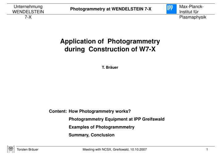
Application of Photogrammetry during Construction of W7-X T. Bräuer. Content: How Photogrammetry works? Photogrammetry Equipment at IPP Greifswald Examples of Photogrammmetry Summary, Conclusion. How Photogrammetry works? Part 1: Principle. Position 3. Position 2. Position 1.

E N D
Application of Photogrammetry during Construction of W7-X T. Bräuer Content: How Photogrammetry works? Photogrammetry Equipment at IPP Greifswald Examples of Photogrammmetry Summary, Conclusion
How Photogrammetry works? Part 1: Principle Position 3 Position 2 Position 1 • Taking a picture from a first camera position • Calculation of first camera position from points known (4 pieces; green lines) in the initial co-ordinate system (blue) • Calculation of line of sight to New-Points (red lines) • Taking pictures from additional camera positions • Repetition of step 2 & 3 for the additional camera positions • Calculation of the cross section of the line of sights to a New-Point and calculation of the 3-D co-ordinate • Finally: Bundle Block Adjustment
Surface point: Retro reflex foil Ø=10mm Adapter for fitted holes Ø=8mmH7 with retro reflex target How Photogrammetry works? Part 2: Marking of Points • Signalization is made by retro reflex targets • Surface points: retro reflective foils (sticky foil) Ø=10mm • Primitive geometries: Adapter for • Fitted holes • edges • corners • … Photogrammtry camera with ring flash Example picture of retro reflective targets with its very high contrast
How Photogrammetry works? Part 3: Identify target points with numbers • Each object point has to has the same number in all pictures! • Coded points are recognized by software image processing • Starting from a minimum of 6 coded points per picture it is possible to name all New-Points of a picture unique
Photogrammetry-Equipment at IPP Greifswald • Measurement system: • 2 x Camera Nikon DX1 • with ring flash • 24mm lense • 20mm lense • 1 x initial cross • 2 x scale bars 1390mm • 512 x coded targets • Software: • AICON 3D-Studio with • Image analysis and co-ordinate calculation • Deformation analysis • Targets: • Sticky foil Ø=10mm for surface • Targets for Ø=8H7 holes • HUBBs-targets • Crossing point • with Offset (usually 25mm) • vector-targets • ball-targets • 3-point-targets • feature-targets • 1.5”-CCR-equivalent
Standfuß 1 Montagestütze 1 u. 2 Messpunkte Ca. 3.5m Druckstütze 2 Zentralstütze 1 u. 2 Planarstütze 1 Standfuß 2 Examples of Photogrammetry Part 1: Incoming inspection of a coil Installation of Photogrammetry targets • Ca. 150 New-Points per coil • Comparison Photogrammetrie and Laser-Tracker: • 12 reference points • RMS = 0.118 mm Survey of coil with Photogrammetry and Laser.Tracker Coil and its Ref.-points
Examples of Photogrammetry Part 2: Survey of coils in assembly stand • ≈ 480 pictures necessary • 83% resp. 95% of points of a coil are visible • Transformation into assembly stand resp. coils co-ordinate system • RMS = 0.13 mm • Maximum position deviation • < 1.2 mm • proof, that measurement accuracy required can be reached • proof, that adjustment accuracy required can be reached
Summery / conclusion • Repetition measurement uncertainty of Photogrammetry is better than 0.1…0.15mm in a volume of 5x5x5m³ • Photogrammetry is appropriated for complex components with a high number of target points • A high number of target points on a component means a high probability to get enough lines of sight • Photogrammmetry do not need rigid stand points for the measurement system • For 4 or more coils assembled in assembly stand Photogrammetry needs less on-line time for a survey than other survey technique (for instant Laser-Tracker) • ------------------------------------------------------------------------------------------------ • Photogrammmetry needs off-line post processing time • Adjustment off components using Photogrammetry needs a lot of affords or is impossible