Download

1 / 51
510 likes | 529 Views
COMP541 Arithmetic Circuits. Montek Singh Mar 26, 2012. Test #1: Take Home. Will assign it Wednesday, 3/28 Give you five days to work on it (due 4/2) Covers topics up to Lecture 15 (Memories II). Today ’ s Topics. Adder circuits How to subtract

E N D
COMP541Arithmetic Circuits Montek Singh Mar 26, 2012
Test #1: Take Home • Will assign it Wednesday, 3/28 • Give you five days to work on it (due 4/2) • Covers topics up to Lecture 15 (Memories II)
Today’s Topics • Adder circuits • How to subtract • Why complemented representation works out so well • Overflow
Iterative Circuit • Like a hierachy, except functional blocks per bit
Adders • Great example of this type of design • Design 1-bit circuit, then expand • Let’s look at • Half adder – 2-bit adder, no carry in • Inputs are bits to be added • Outputs: result and possible carry • Full adder – includes carry in, really a 3-bit adder
Half Adder • S = X Y • C = XY
Full Adder • Three inputs. Third is Cin • Two outputs: sum and carry
Ripple-Carry Adder • Straightforward – connect full adders • Carry-out to carry-in chain • C0 in case this is part of larger chain, or just ‘0’
Hierarchical 4-Bit Adder • We can easily use hierarchy here • Design half adder • Use in full adder • Use full adder in 4-bit adder
Behavioral Verilog // 4-bit Adder: Behavioral Verilog module adder_4_b_v(A, B, C0, S, C4); input[3:0] A, B; input C0; output[3:0] S; output C4; assign {C4, S} = A + B + C0; endmodule Addition (unsigned) Concatenation operation
What’s the Problem with this Design? • Delay • Approx how much? • Imagine a 64-bit adder • Look at carry chain
Delays (Post Place and Route) • Odd delays caused by placement
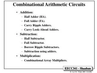
Multibit Adders • Several types of carry propagate adders (CPAs) are: • Ripple-carry adders (slow) • Carry-lookahead adders (fast) • Prefix adders (faster) • Carry-lookahead and prefix adders are faster for large adders but require more hardware. • Adder symbol (right)
Carry Lookahead Adder • Note that add itself just 2 level • Idea is to separate carry from adder function • Then make carry approx 2-level all way across larger adder
Four-bit Ripple Carry Reference Adder function separated from carry Notice adder has A, B, C in and S out, as well as G,P out.
Propagate • The P signal is called propagate • P = A B • Means to propagate incoming carry
Generate • The G is generate • G = AB, so new carry created • So it’s ORed with incoming carry
Said Differently • If A B and there’s incoming carry, carry will be propagated • And S will be 0, of course • If AB, then will create carry • Incoming will determine whether S is 0 or 1
Turn Into Two Gate Delays Design changed from deep (in delay) to wide
C2 Circuit Two Levels G from before and P to pass on This checks two propagates and a carry in
C3 Circuit Two Levels Generate from level 0 and two propagates G from before and P to pass on This checks three propagates and a carry in
What Happens as Scale Up? • Can I realistically make 64-bit adder like this? • Have to AND 63 propagates and Cin! • Compromise • Hierarchical design • More levels of gates
Making 4-Bit Adder Module • Create propagate and generate signals for whole module
Group Propagate • Make propagate of whole 4-bit block • P0-3 = P3P2P1P0
Group Generate • Does G created upstream pass on because of string of Ps (also G3)? • Indicates carry generated in block
Hierarchical Carry A B A B 4-bit adder 4-bit adder S G P Cin S G P Cin C4 C8 Look Ahead C0 Left lookahead block is exercise for you
Practical Matters • FPGAs like ours have limited inputs per block • Instead they have special circuits to make adders • So don’t expect to see same results as theory would suggest
Other Adder Circuits • What if hierarchical lookahead too slow • Other styles exist • Prefix adder (explained in text) had a tree to computer generate and propagate • Pipelined arithmetic units – multicycle but enable faster clock speed • These are for self-study • We might cover later in semester, time permitting
On to Subtraction • First, look at unsigned numbers • Motivates why we typically use complemented representation • Then look at 2’s complement • Imagine a subtractor circuit (next)
One-bit Subtractor M S 1-bit sub Bin Bout D • Inputs: Borrow in, minuend and subtrahend • Review: subtrahend is subtracted from minuend • Outputs: Difference, borrow out • Could use like adder • One per bit
Example If no borrow, then result is non-negative (minuend >= subtrahend). Since there is borrow, result must be negative. The magnitude must be corrected. Next slide.
Correcting Result • What, mathematically, does it mean to borrow? • If borrowing at digit i-1 you are adding 2i • Next Slide
Correcting Result 2 • If M is minuend and N subtrahend of numbers length n, difference was 2n + M – N • What we want is magnitude of N-M (with minus sign in front) • Can get by subtracting previous result from 2n N - M = 2n – (M – N + 2n) This is called 2’s complement
Put Another Way • This is equivalent to how we do subtraction in our heads • Decide which is greater • Swap if necessary • Subtract • Could build a circuit this way… • Or just look at borrow bit
Algorithm • Subtract N from M • If no borrow, then M N and result is OK • Otherwise, N > M so result must be subtracted from 2n (and minus sign prepended)
That Complex Design not Used • That’s why people use complemented interpretation for numbers • 2’s complement • 1’s complement
1’s Complement • Given: binary number N with n digits • 1’s complement defined as (2n – 1) - N
2’s Complement • Given: binary number N with n digits • 2’s complement defined as 2n – N for N 0 0 for N = 0 • Exception is so result will always have n bits • 2’s complement is just a 1 added to 1’s complement
Observations • 1’s C and Signed Mag have two zeros • 2’s C has more negative than positive • All negative numbers have 1 in high-order
Adder-Subtractor • Need only adder and complementer for input to subtract • Need selective complementer to make negative output back from 2’s complement • Or go through adder again. See next slide
Advantages/Disadvantages • Signed magnitude has problem that we need to correct after subtraction • One’s complement has a positive and negative zero • Two’s complement is most popular • Arithmetic operations easy
Conclusion: 2’s Complement • Addition easy on any combination of positive and negative numbers • To subtract • Take 2’s complement of subtrahend • Add • This performs A + ( -B), same as A – B
Design of Adder/Subtractor Output is 2’s complement if B > A S low for add, high for subtract Inverts each bit of B if S is 1 Adds 1 to make 2’s complement
Overflow • Two cases of overflow for addition of signed numbers • Two large positive numbers overflow into sign bit • Not enough room for result • Two large negative numbers added • Same – not enough bits • Carry out can be OK
Overflow Examples 4-bit signed numbers: • Sometimes a leftmost carry is generated without overflow: • -7 + 7 • 5 + (-3) • Sometimes a leftmost carry is not generated, but overflow occurs: • 4 + 4
Overflow Detection • Basic condition: • if two +ve numbers are added and sum is –ve • if two -ve numbers are added and sum is +ve • Can be simplified to the following check: • either Cn-1 or Cn is high, but not both