Download
1 / 1
40 likes | 201 Views
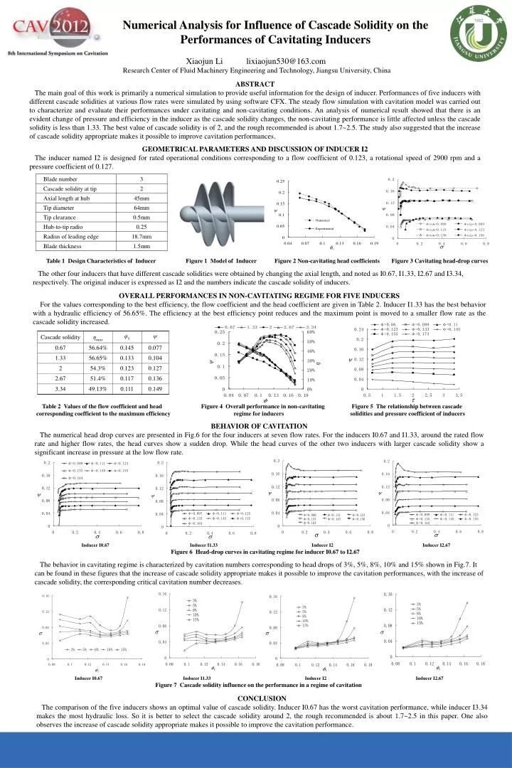
Numerical Analysis for Influence of Cascade Solidity on the Performances of Cavitating Inducers. Xiaojun Li lixiaojun530@163.com Research Center of Fluid Machinery Engineering and Technology, Jiangsu University, China. ABSTRACT

E N D
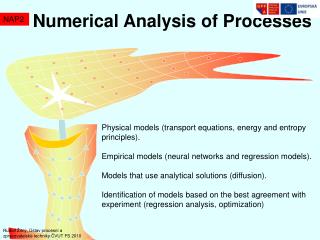
Numerical Analysis for Influence of Cascade Solidity on the Performances of Cavitating Inducers XiaojunLilixiaojun530@163.com Research Center of Fluid Machinery Engineering and Technology, Jiangsu University, China ABSTRACT The main goal of this work is primarily a numerical simulation to provide useful information for the design of inducer. Performances of five inducers with different cascade solidities at various flow rates were simulated by using software CFX. The steady flow simulation with cavitation model was carried out to characterize and evaluate their performances under cavitating and non-cavitating conditions. An analysis of numerical result showed that there is an evident change of pressure and efficiency in the inducer as the cascade solidity changes, the non-cavitating performance is little affected unless the cascade solidity is less than 1.33. The best value of cascade solidity is of 2, and the rough recommended is about 1.7~2.5. The study also suggested that the increase of cascade solidity appropriate makes it possible to improve cavitation performances. GEOMETRICAL PARAMETERS AND DISCUSSION OF INDUCER I2 The inducer named I2 is designed for rated operational conditions corresponding to a flow coefficient of 0.123, a rotational speed of 2900 rpm and a pressure coefficient of 0.127. Table 1 Design Characteristics of Inducer Figure 1 Model of Inducer Figure 2 Non-cavitating head coefficients Figure 3 Cavitating head-drop curves The other four inducers that have different cascade solidities were obtained by changing the axial length, and noted as I0.67, I1.33, I2.67 and I3.34, respectively. The original inducer is expressed as I2 and the numbers indicate the cascade solidity of inducers. OVERALL PERFORMANCES IN NON-CAVITATING REGIME FOR FIVE INDUCERS For the values corresponding to the best efficiency, the flow coefficient and the head coefficient are given in Table 2. Inducer I1.33 has the best behavior with a hydraulic efficiency of 56.65%. The efficiency at the best efficiency point reduces and the maximum point is moved to a smaller flow rate as the cascade solidity increased. Table 2 Values of the flow coefficient and head Figure 4 Overall performance in non-cavitating Figure 5 The relationship between cascade corresponding coefficient to the maximum efficiency regime for inducers solidities and pressure coefficient of inducers BEHAVIOR OF CAVITATION The numerical head drop curves are presented in Fig.6 for the four inducers at seven flow rates. For the inducers I0.67 and I1.33, around the rated flow rate and higher flow rates, the head curves show a sudden drop. While the head curves of the other two inducers with larger cascade solidity show a significant increase in pressure at the low flow rate. Inducer I0.67 Inducer I1.33 Inducer I2 Inducer I2.67 Figure 6 Head-drop curves in cavitating regime for inducer I0.67 to I2.67 The behavior in cavitating regime is characterized by cavitation numbers corresponding to head drops of 3%, 5%, 8%, 10% and 15% shown in Fig.7. It can be found in these figures that the increase of cascade solidity appropriate makes it possible to improve the cavitation performances, with the increase of cascade solidity, the corresponding critical cavitation number decreases. Inducer I0.67 Inducer I1.33 Inducer I2 Inducer I2.67 Figure 7 Cascade solidity influence on the performance in a regime of cavitation CONCLUSION The comparison of the five inducers shows an optimal value of cascade solidity. Inducer I0.67 has the worst cavitation performance, while inducer I3.34 makes the most hydraulic loss. So it is better to select the cascade solidity around 2, the rough recommended is about 1.7~2.5 in this paper. One also observes the increase of cascade solidity appropriate makes it possible to improve the cavitation performance.