Download
1 / 30
300 likes | 523 Views
Introduction TDR Technical Design Review. Barry Barish TDR Technical Design Review KEK Laboratory 13-Dec-12. A Global Initiative for an ILC. International Committee for Future Accelerators (ICFA) representing major particle physics laboratories worldwide.

E N D
Introduction TDR Technical Design Review Barry Barish TDR Technical Design Review KEK Laboratory 13-Dec-12 Global Design Effort
A Global Initiative for an ILC International Committee for Future Accelerators (ICFA) representing major particle physics laboratories worldwide. • Chose ILC accelerator technology (SCRF) • Determined ILC physics design parameters • Formed Global Design Effort and Mandate (TDR) Global Design Effort
HEP Lab-driven R&D programs Room temperature copper structures (KEK and SLAC) OR Superconducting RF cavities (DESY) Global Design Effort 3
ITRP in Korea Linear Collider School 2012 Lecture I-2
Key Parameters Luminosity ∫Ldt = 500 fb-1 in 4 years Ecm adjustable from 200 – 500 GeV Ability to scan between 200 and 500 GeV Energy stability and precision below 0.1% Electron polarization of at least 80% ILCSC/ICFA Parameters Studies physics driven input Options • The machine must be upgradeable to 1 TeV • Positron polarization desirable as an upgrade Global Design Effort
GDE -- Design a Linear Collider Superconducting RF Main Linac Global Design Effort 6
GDE – Mandate (7-Feb 06) Global Design Effort 7
Reference Design - 2008 Global Design Effort
RDR Design Parameters Global Design Effort
Design decisions accepted globally! Global Design Effort
Push – Pull Detector Concept Both detectors without platforms Both detectors with platforms • Vibration stability will be one of the major criteria in eventual selection of a motion system design Global Design Effort
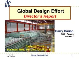
Major R&D Goals for Technical Design SCRF High Gradient R&D - globally coordinated program to demonstrate gradient by 2010 with 50%yield; improve yield to 90% by TDR (end 2012) Manufacturing: plug compatible design; industrialization, etc. Systems tests: FLASH; plus NML (FNAL), STF2 (KEK) post-TDR Test Facilities ATF2 - Fast Kicker tests and Final Focus design/performance EARTHQUAKE RECOVERY CesrTA - Electron Cloud tests to establish damping ring parameters/design and electron cloud mitigation strategy FLASH – Study performance using ILC-like beam and cryomodule (systems test) Global Design Effort Global Design Effort
Globally Coordinated SCRF R&D • Achieve high gradient (35MV/m); develop multiple • vendors; make cost effective, etc • Focus is on high gradient; production yields; cryogenic • losses; radiation; system performance Global Design Effort
Progress in Cavity Gradient Yield Production yield: 94 % at > 28 MV/m, Average gradient: 37.1 MV/m Global Design Effort
Global Plan for SCRF R&D We are here Global Design Effort
Accelerator Test Facility (ATF) Global Design Effort
ATF-2 earthquake recovery • Vertical beam size (2012) = 167.9 plus-minus nm • 1 sigma Monte Carlo • Post-TDR continue to ILC goal of 37 nm + fast kicker • Stabilization studies Global Design Effort
CesrTA - Wiggler Observations 0.002”radius Electrode a best performance Global Design Effort
Baseline Mitigation Plan *Drift and Quadrupole chambers in arc and wiggler regions will incorporate antechambers • Preliminary CESRTA results and simulations suggest the presence of sub-threshold emittance growth • Further investigation required • May require reduction in acceptable cloud density a reduction in safety margin • An aggressive mitigation plan is required to obtain optimum performance from the 3.2km positron damping ring and to pursue the high current option Global Design Effort
Plan for TDR Global Design Effort
Proposed Design changes for TDR RDR SB2009 • Single Tunnel for main linac • Move positron source to end of linac *** • Reduce number of bunches factor of two (lower power) ** • Reduce size of damping rings (3.2km) • Integrate central region • Single stage bunch compressor Global Design Effort
ILC TDR Layout Damping Rings Polarised electron source Ring to Main Linac (RTML) (inc. bunch compressors) e+ Main Linac Beam Delivery System (BDS) & physics detectors Beam dump Polarised positronsource e- Main Linac not too scale Global Design Effort
Candidate Sites in Japan Global Design Effort
Tunnels in the Japanese Mountains New Tunnel Shape Grooved Insert for CesrTA Wiggler • Japanese initiative for hosting the ILC • Higgs Factory / Staged approach • Developed through International Collaboration • Linear Collider Collaboration (Lyn Evans – Director) Global Design Effort
TDR – Site Dependent Design TDR (common) • Core requirements • Accelerator layout • Technologies Major site-dependent differences • Conventional Facilities • High Level RF Global Design Effort
Upgrades – Luminosity RF parameters for luminosity upgrade – Chapter 12 • Doubling average beam power requires additional RF power (klystrons and modulators) for the main linacs and modifications to the damping rings. • Other systems already specified for higher beam power (larger number of bunches per pulse). Global Design Effort
Upgrades - Energy Energy upgrade scenarios – Chapter 12 • Upgrading the beam energy will require extending the main SCRF linacs to provide the additional 250 GeV per beam. • The beam current for the TeV upgrade (7:6 mA), less than that for the luminosity upgrade (8:8 mA) • The cost of an energy upgrade is completely dominated by the extension of the main linacs and the time-dependent choice of accelerating gradient. (present three scenarios) Global Design Effort
Higgs Factory - Staged ILC 250 GeV (Higgs Factory) 500 GeV baseline 1 TeV • Table 12.1 presents primary parameters for a 250 GeV CM first stage, the luminosity upgrade for the 500 GeV baseline machine, and the two parameter sets for the TeV upgrade: low Beamstrahlung (A) and high Beamstrahlung (B). The baseline 500 GeV parameters are included for reference. • The initial 250 GeV stage (Light Higgs Factory) needs a re-evaluation of machine parameters for cost-performance optimization at that energy. Global Design Effort
Project Implementation Planning Possible Roadmap to an ILC Global Design Effort
Final Remarks and Conclusions The TDR completes the mandate for the ILC The major milestones in the R&D program have been achieved and a detailed conceptual design for the ILC has been produced, including a new value costing • A new integrated Linear Collider Collaboration (LCC) under ICFA, including ILC, CLIC and Detectors/Physics will carry out the next steps toward realization of an ILC Global Design Effort