Download
1 / 18
230 likes | 291 Views
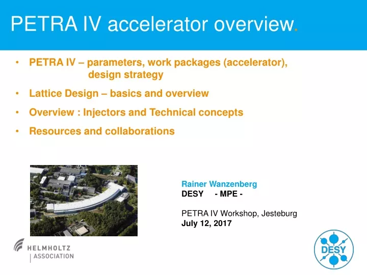
PETRA IV accelerator overview. PETRA IV – parameters, work packages (accelerator), design strategy Lattice Design – basics and overview Overview : Injectors and Technical concepts Resources and collaborations. Rainer Wanzenberg DESY - MPE -

E N D
PETRA IV accelerator overview. • PETRA IV – parameters, work packages (accelerator), design strategy • Lattice Design – basics and overview • Overview : Injectors and Technical concepts • Resources and collaborations Rainer Wanzenberg DESY - MPE - PETRA IV Workshop, Jesteburg July 12, 2017
PETRA IV – parameters parameters from the application for road map process: Approach: Investigate most challenging design parameters (6 GeV, 10 pm) ! bare lattice emittance ~ 20 pm use damping undulators / wigglers to mitigate IBS and reduce the emittance ~10 pm (low bunch charge) Topic for discussion at this meeting
PETRA IV preparation project: WP 2 accelerators 2.01 Lattice design RW Design Strategy • Investigation of the technical limits and possibilities • at an early stage before a lattice design is finalized • Focus on criticalsystem 2.02a Preaccelerator: synch. Heiko Ehrlichmann 2.03a Technical Concepts Magnets, Girder Markus Körfer 2.02a Preaccelerator: linac Markus Hüning 2.03b Technical Concepts Vacuum System Ralph Boespflug, Lutz Lilje Comment from the MAC, May 2017: Furthermore, the CDR should look at all technical systems, including systems that are not judged to be technically challenging at this stage of the study (for example BPMs, feedbacks, …). 2.03c Technical Concepts RF Michael Ebert
Design Strategy (Status Nov. 2016) Design goal: get an large dynamic acceptance, an on axis injection with the existing injector should be possible Lattice Design • Design based on a scaled ESRF cell • and further investigation of lattice variants • Phase spaceexchangesolution (double twist in 4D-phase) • arc cell with phase advance of p between sextupoles • investigation for an appropriate undulator cell (modified scaled ESRF cell) Injectors Design goal: reuse most parts of injector chain • studies to improve emittance, including a new lattice for the synchrotron • investigation of the technical requirements to maintain operation until 2045 • studies toward a new injector: additional booster ring, or linac Technical design Investigation of the technical limits and possibilities at an early stage before a lattice design is finalized • magnet design: design studies of quads, combined function magnets and • dipoles with longitudinal gradient • girder design: investigation of concepts with new materials, • studies of alignment and installation concepts • fast kickers: on axis injection • vacuum design: modeling of the system with small chambers
Lattice Design: Horizontal emittance Horizontal emittance in electron storage ring: radiation damping equilibrium quantum excitation increase radiated power paywith RF-power
Lattice design: small emittance Horizontal emittance in electron storage ring: radiation damping equilibrium quantum excitation (6 GeV / 5 GeV)2 = 1.44 normalized energy loss per turn normalized quantum excitation rate Minimum quantum excitation keep off-momentum orbit close to nominal orbit minimize dispersion at locations of radiation (bends) Multibend achromat: many small dipoles, longitudinal bends
Multi bend achromats MAX IV, 3 GeV, ex = 200 … 330 pm ESRF - EBS, 6 GeV, ex = 133 pm Extremely Brilliant Source APS - U, 6 GeV, ex = 41 pm Hybrid seven bend achromat based on concept from ESRF
PETRA III compared to APS, ESRF, Spring 8 long straight sections: 4 x 108.0 m = 432.0 m short straight sections: 4 x 64.8 m = 259.2 m arcs : 8 x 201.6 m = 1612.8 m C ~ 2304 m (2303.9525 m) e = 1.3 nm with Damping Wigglers APS E = 7 GeV C = 1104 m e = 3.1 nm 40 cells: 27.6 m New octant: 1 cell NE and ½ + 8 + ½ = 9 cells: 23 m with canting 4 cells: P02/03 P05/06 P11/12 P13/14 ESRF E = 6 GeV C = 844 m e = 3.8 nm 32 cells: 26.4 m Spring-8 E = 8 GeV C = 1436 m e = 3.4 nm 36+8 = 44 cells: ~30 m
PETRA III PETRA IV: Lattice change DBA MBA Lattice Design – step 1 MBA cell (Multi Bend Achromat cell) with small emittance Hybrid sevenBend Achromat (scaled from ESRF) H7BA cell, length 23 m bare Emittance 12 pm without collective effects: IBS = Intra Beam Scattering DBA octant: ½ + 8 + ½ cells (23 m) 18 dipoles (43.3 mrad) L = 1 m + 5 canting dipoles ( 5 mrad) L = 0.3 m 2 dipoles / cell Hybrid with dispersion bump
Lattice design – step 2: Non linear dynamics Sextupole magnets are needed to correct chromatic aberrations Chromatic sextupoles guarantee the focussing of off-energy particles In PETRA III sextupoles are only installed in the FODO arcs ! Sextupoles have a strong impact on the non linear dynamics of the beam d = energy deviation this term is wanted
Lattice design: step 2, dynamic acceptance Lattice design step 2: Optimization of the non linear dynamics track particle with amplitude x for ~ 2000 turns Lattice design step 1: HMBA cell with small emittance, scaled ESRF cell: 12 pm·rad at 6 GeV Some quadrupoles too strong, g < 120 T/m Dynamic Acceptance (DA) is too small example: DA = 0.3 mm mrad optical function b ~ 21 m dynamic aperture 2.5 mm βx=21.9 mβy=20.9 m Not optimized • PETRA-IV lattice design J. Keil
Lattice design: step 3, collective effects Intra beam scattering (IBS): multiple small-angle Coulomb scatterings of electrons within the beams • Emittance growth growth rate: Wakefields and Instabilities • geometrical wakefields • resistive wall wakefields kick parameter per length PETRA III @ 3 GeV, July 2013 480 bunches, 50 mA, N = 5x10⁹, 310 pm conductivity scales with the 3rd power of the beam pipe radius 480 bunches, 5 mA, N = 5x10⁸, 160 pm
WP: Injectors • Design goal: reuse/up-grade the injector chain • Linac • S-Band Linac (450 MeV) • PIA (accumulator ring) • 10 ns Linac pulse 500 MHz bucket • DESY II • 450 MeV 7 GeV, • Emittance (6 GeV) x/y ~ 350/15 nm • Intensity: max. 2 x 10¹⁰, typical 1 x 10¹⁰ • Studies have started on the possibilities to improve the booster emittance • With beam optics optimization + damping partition shift of present optics • one may get ~200nm @6GeV • Rebuilding ring with smaller emittance lattice: DESY IV • scaling the ALBA booster 10 nm @6GeV
PETRA IV booster DESY IV (scaling the ALBA booster) C = 300 m ex = 7 nm (equilibrium) DESY II (different working points ) The ejection scheme is optimized for working point 1 presently used working point 320 nm·rad workingpointwith bestemittance ~180 nm·rad localminimum ~280 nm·rad The presently installed quad power supplies do not allow an operation at working point 3 with full energy. (Courtesy Dieter Einfeld)
PETRA IV project study: time schedule we are here lattice selected Project preparation phase 1/16 – 12/19 MAC Typical time to finalize a lattice design: PEP-X: 3 years, ESRF: 5 years Challenge: PETRA IV lattice design with in 1 ½ … 2 years Goal: Conceptual Design Report 4/2018
Resources Organisation: Matrix Structure Accelerators and Projects Linac, DESY, PETRA III, … , FLASH, XFEL Groups: RF Vacuum Accelerator Physics … Insertion Devices (Photon Science Research Division) PETRA III / IV accelerator physics team: Ilya Agapov, Joachim Keil,Gajendra K. Sahoo 2.5 FTE allocated to PETRA IV Xavier Nuel Gavalda (Feb. 1, 2017) Further resources for PETRA IV (lattice design), the hiring process was successful: 2FTE • investigation of collective effects (impedance model) Yong-ChulChae (June 15, 2017) • injector design, new booster JieXiZhang (July 2017) • investigation of lattice tolerances with respect to errors 1 FTE starting in Oct 2017 • an additional FTE will be available • Additional resources for PETRA IV (vacuum group) • Nils Plambeck (Vacuum system) (Jan., 2017) 1 FTE
Collaborations • ESRF • supporting the lattice design, sharing lattice files • recently (June 2017) visit to ESRF • visit from ESRF is planned for Aug. 2017 • Mikael Eriksson • joined the PETRA IV project preparation as a generalist from June 2016 • SLAC – DESY collaboration • visit to SLAC in Oct 2016 (host Bob Hettel) • discussing on lattice theory, impedance and collective effects • Yunhai Cai visited DESY in April, LEGO, lie algebra methods • Efremov institute - DESY collaboration: magnet design • Technical University of Darmstadt: RF calculation, 100 MHz cavity • (next collaboration meeting in Oct.)