Download
1 / 47
480 likes | 682 Views
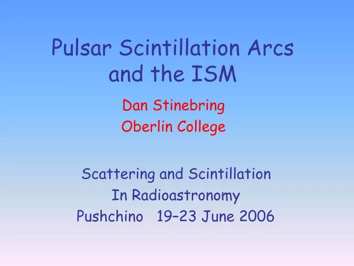
Pulsar Scintillation Arcs and the ISM. Dan Stinebring Oberlin College. Scattering and Scintillation In Radioastronomy Pushchino 19–23 June 2006. Collaborators. Bill Coles Jim Cordes Barney Rickett Volodya Shishov Tania Smirnova and many Oberlin College students. Motivations.

E N D
Pulsar Scintillation Arcsand the ISM Dan Stinebring Oberlin College Scattering and Scintillation In Radioastronomy Pushchino 19–23 June 2006
Collaborators • Bill Coles • Jim Cordes • Barney Rickett • Volodya Shishov • Tania Smirnova • and many Oberlin College students
Motivations • Interstellar inhomogeneity spectrum • Single-dish “imaging” of the ISM on AU size scales on a continuing basis • Imaging the pulsar magnetosphere? • Improving high-precision pulsar timing • Reducing the effects of scattering
0834+06 with Secondary Differential Delay Differential Doppler Shift
B2021+25 B0450–18
B1540–06 340 MHz
“Deflection of Pulsar Signal Reveals Compact Structures in the Galaxy, ” A. S. Hill et al. 2005, 619, L17
Key Points • 1) scintillation arcs are detectable toward most bright pulsars • 2) they provide single-dish snapshots of the 2d distribution of scattering material (fov ~ 40 mas; ~ 4 mas) • 3) they scan the sky at the large proper motion rate of most pulsars
Coherent radiation scatters off electron inhomogeneities
Multi-path interference causes a random diffraction pattern
Relative transverse velocities produce a dynamic spectrum time
Scattering in a thin screen plus a simple core/halo model can explain the basics of scintillation arcs
Hierarchy of Power Levels • Core-core • Core-halo • Halo-halo Near origin of SS Holographic Imaging Main scintillation arc features Too weak to detect
Kolmogorov vs. Gaussian PSF How to produce a “core/halo” psf? A Gaussian psf will NOT work: No halo.
Kolmogorov vs. Gaussian PSF Kolmogorov turbulence DOES work It produces a psf with broad wings
Fringe frequencies Doppler Delay Veff
Fringe frequencies Doppler Delay Veff Ds D
Fringe frequencies Doppler Delay What if (point source at the origin) Then So that Veff Parabolic arc with a positive definite offset
Fringe frequencies Doppler Delay Curvature of the Parabola Veff
Secondary spectrum basics Curvature of the parabola Determine screen location D, l, V known Measure
450 pc 640 pc Needed: shallow (Kolmogorov) spectrum and “thin-screen” geometry –25 25 x (mas)
Multiple Scintillation Arcs: • Each is telling us about a scattering “screen” along the los • The curvature of the arc (plus distance and proper motion info) locates the screen along the los • Sharp arc boundaries imply thin screens • Screen locations are constant over decades of time see Putney et al. poster for details
Effective Velocity Cordes and Rickett 1998, ApJ, 507, 846
Hill, A.S., Stinebring, D.R., et al. 2005, ApJ,619, L171 The patchiness MOVES ! This is the angular velocity of the pulsar across the sky!
Hill, A.S., Stinebring, D.R., et al. 2005, ApJ,619, L171 There is considerable bending power in the entities that give rise to the arclet features (a - d). Our estimates: Size ~ 1 AU Density ~ 200 cm-3 Are these the same objects that give rise to ESEs?
Holographic Imaging (very early stages)
Mark Walker has made substantial progress on finding underlying “scattered wave components” in a secondary spectrum. Walker, M.A. & Stinebring, D.R. 2005, MNRAS, 362, 1269
It may be possible to form an image of the scattering material in the ISM with milliarcsecond resolution. The searchlight beam that illuminates the medium is swept along by the pulsar proper motion. (Work in progress with Mark Walker and others …)
Summary Comments • There are many opportunities for focused observational projects • Early stage of interpretation of results: many fundamental puzzles remain! • Larger more sensitive telescopes will provide breakthroughs!
Some references Observation • Stinebring et al. 2001, ApJ, 549, L97 • Hill et al. 2003, ApJ, 599, 457 • Hill et al. 2005, ApJ, 619, L17 Theory • Walker et al. 2004, MNRAS, 354, 43 • Cordes et al. 2006, ApJ, 637, 346 • Walker & Stinebring 2005, MNRAS, 362, 1279