Download
1 / 67
1.09k likes | 1.9k Views
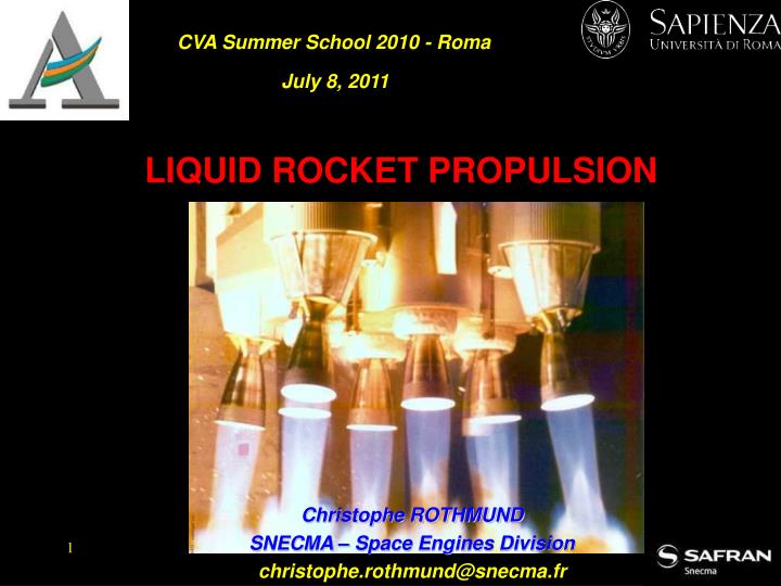
CVA Summer School 2010 - Roma. July 8, 2011. LIQUID ROCKET PROPULSION. Christophe ROTHMUND SNECMA – Space Engines Division christophe.rothmund@snecma.fr. CONTENTS. Part 1 : LIQUID ROCKET ENGINES Part 2 : NEAR TERM PROPULSION SYSTEMS Part 3 : ELECTRIC PROPULSION.

E N D
CVA Summer School 2010 - Roma July 8, 2011 LIQUID ROCKET PROPULSION Christophe ROTHMUND SNECMA – Space Engines Division christophe.rothmund@snecma.fr
CONTENTS Part 1 : LIQUID ROCKET ENGINES Part 2 : NEAR TERM PROPULSION SYSTEMS Part 3 : ELECTRIC PROPULSION Part 1 : LIQUID ROCKET ENGINES Part 2 : ANATOMY OF A ROCKET ENGINE Part 3 : TEST FACILITIES Part 4 : NUCLEAR PROPULSION Part 4 : ANATOMY OF A ROCKET ENGINE Part 5 : ADVANCED PROPULSION
Part 1 LIQUID ROCKET ENGINES
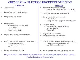
LIQUID ROCKET ENGINE TYPES SOLID GRAIN NUCLEAR REACTOR NUCLEAR THERMAL FUEL
LIQUIDPROPELLANTS MONOPROPELLANTS : Hydrazine, Hydrogen peroxyde BIPROPELLANTS : OXIDIZERS : FUELS : Kerosine, ethanol Liquid hydrogen, UDMH, MMH, Hydrazine Liquid oxygen, N2O4, Hydrogen peroxyde
HYBRID PROPELLANTS liquid propellant : oxidizer - solid propellant : fuel (solid oxidizers are problematic and lower performing than liquid oxidizers) Solid fuels (HTPB or paraffin) allow for the incorporation of high-energy fuel additives (e.g.aluminium).
CHEMICAL REACTIONS BIPROPELLANTS Dimethylhydrazine (UDMH) : H2N – N (CH3)2 (l)+ 2 N2O4 (l) - > 3 N2 (g) + 4 H2O (g) + 2 CO2 (g) Hydrazine hydrate (N2H4,H2O) : 2 (N2H4,H2O) (l) + N2O4 (l) - > 3 N2 (g) + 6 H2O (g) Monomethylhydrazine (MMH) : 4 H2N – NHCH3 (l) + 5 N2O4 (l) - > 9 N2 (g) + 12 H2O (g) + 4 CO2 (g) Kerosene (CH2 is the approximate formula ) with hydrogen peroxide : CH2 + 3H2O2 → CO2 + 4H2O Kerosene and liquid oxygen (LOX) CH2 + 1.5O2 → CO2 + H2O Hydrogen and oxygen (liquids) : 2 H2 (g)+ O2 (g) - > 2 H2O (g) MONOPROPELLANTS Hydrogen peroxyde (H2O2) H2O2 (l) - > H2O (l) + 1/2 O2 (g) Hydrazine (N2H4) N2H4 (l) - > N2 (g) + 2 H2 (g)
PROPULSION BASICS Pressure-fed cycle • Pros : • Simplicity • Low complexity • Cons : • Low performance • Oldest and simplest cycle, • Rarely used nowadays on launch vehicles, • Powered France’s Launch vehicle family Diamant.
Gas-generator cycle • Pros : • Higher presssures • Lowerturbine temperatures • Highest performance • Cons : • Moderate performance • Most widely used cycle in the western world,
Preburner cycle • Pros : • Higher presssures • Lowerturbine temperatures • Highest performance • Cons : • High complexity • Used on the Shuttle and the H-2A main engine
Expander cycle • Pros : • Thermally challenging • Highest performance • Cons : • For cryogenic engines only • Limited power therefore not suited for high thrusts • Oldest cryogenic engine in service (RL-10) • Used in Japan and Europe
Full flow staged combustion rocket cycle • Pros : • Higher presssures • Lowerturbine temperatures • Highest performance • Cons : • Very high complexity • Never flown, • Demonstration only (IPD) so far
Hybrid rocket cycle • Pros : • Higher performance than solids • Lower complexity than liquids • Cons : • Lower performance than liquids • Higher complexity than solids
Nuclear thermal rocket cycle • Pros : • Highest performance • Cons : • Very high complexity • Radiations • Never flown, • Demonstration only so far
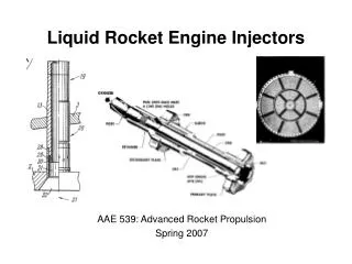
THRUST CHAMBER ASSEMBLY GIMBAL Chamber Characteristics: • Combustion • High pressure • High temperature • Very low net fluid velocity INJECTOR COMBUSTION CHAMBER Exit Characteristics: • Flow expands to fill enlarged volume • Reduced pressure • Reduced temperature • Very high fluid velocity NOZZLE EXTENSION
Nozzle design challenges Structural factors Structural concerns • Loads • Testing • Altitude Simulation or Sea Level • Sideloads • Flight • Lift off, shut down, restart • Sideloads • Transportation • Temperature • Physical • Weight, Center of Gravity • Service Life • Running time, Number of starts • Duty Cycle/Operating Range • Continuous operation at one power level • Throttled operation • Materials • Compatibility • Strength, • Heat transfer capability June 16, 1997
KEY REQUIREMENTS FOR SAFE NOZZLE OPERATION • Sea level : • - stable operation on ground • high performance • Vacuum : • - high vacuum performance • - low package volume Bell nozzle Advanced concepts with altitude adaptation Dual-bell nozzle Extendible nozzle Plug nozzle (“Aerospike”)
Nozzle Types • Conical Nozzle • Simple cone shape - easy to fabricate • Rarely used on modern rockets • Bell Nozzle • Bell shape reduces divergence loss over a similar length conical nozzle • Allows shorter nozzles to be used • Annular Nozzles (spike or pug) • Altitude compensating nozzle • Aerospike is a spike nozzle that uses a secondary gas bleed to “fill out” the truncated portion of the spike nozzle
Nozzle extension cooling systems Laser welded jacket to liner Brazed tubes inside jacket Brazed jacket to liner Materials : stainless steel, copper, nickel, copper/nickel
AEROSPIKE NOZZLES Linear aerospike Rocketdyne XRS-2200 Rocketdyne AMPS-1 1960’s World’s first aerospike flight, September 20, 2003 (California State Univ. Long Beach) Annular aerospike
Part 2 ANATOMY OF A ROCKET ENGINE 1 – Gas generator cycle : F-1 and Vulcain engines 2 – Staged combustion cycle : SSME 3 – Expander cycle : Vinci 4 – Linear aerospike XRS2200 5 – Nuclear : NERVA/RIFT
Engine flow diagram Rocketdyne F-1
Engine characteristics Rocketdyne F-1
Engine components Rocketdyne F-1
TESTS AND LAUNCHES 100 m 1000 m
Vulcain 1 Vulcain 2 Engine characteristics VULCAIN 2 Vacuum thrust 1140 kN 1350 kN Mixture ratio 4,9 to 5,3 6,13 Vacuum specific impulse 430 s 434 s Dry weight 1680 kg 2040 kg Chamber pressure 110 bar 116 bar Expansion ratio 45 60 Design life 6000 s 20 starts 5400 s 20 starts
Vulcain 2 Flow diagram VULCAIN 2
VULCAIN 2 Thrust chamber
VULCAIN 2 Hydrogen turbopump 34200 rpm, 11,3 MW
VULCAIN 2 Oxygen turbopump 13300 rpm, 2,9 MW
SSME Engine characteristics SSME Propellants LOX – LH2 Vacuum thrust at 109 % 2279 kN Mixture ratio 6 Vacuum specific impulse 452 s Dry weight 3527 kg Chamber pressure 206,4 bar Expansion ratio 69 Throttle range 67 % - 109 % Design life 7,5 hours 55 starts
SSME Flow schematic SSME 6,9 bar 2,07 bar 190,3 bar 29,1 bar 511,6 bar 296,5 bar 450 bar 206,4 bar
SSME SSME Powerhead Fuel Preburner Oxidizer Preburner Main chamber Oxygen Hydrogen
F1 vs. SSME test comparison SSME Last Planned SSME Test : July 29, 2009 Duration : 520 sec, NASA Stennis
FLOW DIAGRAM VINCI
Vinci Engine characteristics VINCI Propellants LOX – LH2 Vacuum thrust 180 kN Mixture ratio 5,80 Vacuum specific impulse 465 s Chamber pressure 60 bar Expansion ratio 240
VINCI Hydrogen turbopump
VINCI Oxygen turbopump
VINCI Combustion chamber 122 co-axial injection elements 228 cooling channels
VINCI Nozzle extension
TYPICAL SMALL ENGINES BIPROPELLANT MONOPROPELLANT Typical applications: Attitude control Roll control Soft landings (Moon, Mars, …)