Download
1 / 21
210 likes | 321 Views
Heart Monitor. Senior Design II - ECE 4522 Mississippi State University Department of Electrical Engineering. Team Members. Advisor: Dr. Lori Bruce bruce@ece.msstate.edu. Team Leader: K’lvin Sui kvs1@ece.msstate.edu. Todd Peacock tpp1@ece.msstate.edu. Craig Williamson

E N D
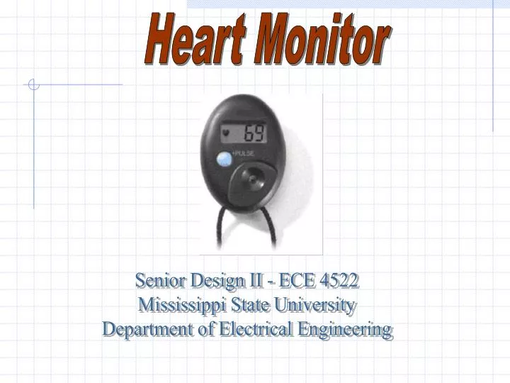
Heart Monitor Senior Design II - ECE 4522 Mississippi State University Department of Electrical Engineering
Team Members Advisor: Dr. Lori Bruce bruce@ece.msstate.edu Team Leader: K’lvin Sui kvs1@ece.msstate.edu Todd Peacock tpp1@ece.msstate.edu Craig Williamson lcw1@ece.msstate.edu Chong Meng Teh ct3@ece.msstate.edu
Team Responsibilities • Todd Peacock • Filter • Comparator • Micro-controller frequency detection • Optical Signal generation and detection • Documentation • Craig Williamson • Filter • Comparator • Optical Signal generation and detection • Packaging • Documentation • Voon Siong K’lvin Sui • PCB Layout • Micro-controller LED programming • Power Consumption • Documentation • Chong Meng Teh • Web page • PCB layout • Packaging • Documentation
Motivation • A heart rate monitor that is accurate, affordable, and easy to use is essential to ensure one’s health quality • Current heart rate monitors are either too expensive, inaccurate, or not user friendly
Problem Statement • Design a heart rate monitor that is accurate, inexpensive, safe, and easy to use • To achieve better accuracy than current optical technology • Compete with the prices of current optical heart monitors • Provide a safe and non-invasive design • Technical problems: • Detecting the pulse using optical techniques • Extracting the pulse signal • Digitizing the signal • Power the device using a 3v lithium battery
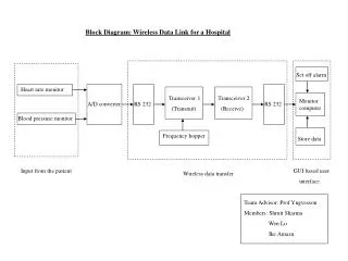
Design Requirements 1. Pulse acquisition: • Light Transmitter: The transmitter will be a red LED light source to reflect the pulse signal from changes in reflectivity caused by changes in blood flow in the index finger. • Pulse Receiver: The receiver will be a photo-sensor that will detect the pulse signal, by sensing attenuations from the transmitted light through an index finger, and create an output voltage in the range of 10 mVpp.
Design Requirements • 2. Signal Extraction:A low pass filter and amplifier will be designed to remove noise from ambient light and level detection distortions. • Cutoff frequency of 4 Hz (200 BPM max heart rate) • SNR of –14 dB before filtering • Need an SNR of 20 dB for the comparator to operate • Roll off rate of 40 dB/dec (second-order butterworth) • Attenuation of 60 Hz noise by 47 dB • Amplification of pass-band frequencies by 40 dB
Design Requirements • 3. Pulse Digitization:The conditioned signal will be analyzed by a comparator to produce a digital pulse. • 1 Vpp output digital pulse • Time between rising pulse edges corresponds to heart rate period
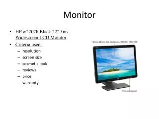
Design Requirements • 4. Display:The heart rate will be displayed on a 3-digit LED display. • Pulse rates measured between 0 < pulse rate < 200
Design Requirements • 5. Accuracy:Due to noise, there will be distortion. Currently available optical heart monitors have a range of +/- 10-15% error. • The design will measure heart rate with no more than +/- 10% error. • Dynamic pulse averaging is used to give a better distribution of accuracy over the full range of pulses. • 6. Power: • The device will consume less than 30 mA • 3 volt lithium battery with a capacity of 1000 mAh • The battery will last 1 year with typical usage. • A watch battery will be used to compact the design.
Design Requirements • 7. Physical Packaging: • Design will be close to the size of a standard stopwatch. • Final packaged dimensions will not exceed 2.5” x 1.7” x 1” (H x W x D). ( rectangular shaped plastic enclosure)
Design Requirements 8. Cost:The component cost should not exceed $30.00. The production cost should not exceed $90.00.
Technical Problems Accuracy: A 10% error in accuracy has not been achieved Solution: The micro-controller is being debugged for syntax error
Summary • Current Status: • Pulse Detector Circuit – Complete • Filter – Complete • Comparator – Complete • Micro-controller – Debugging • Packaging – Incomplete • PCB Layout – Complete • Fabricated PCB -- Incomplete