Download

1 / 45
450 likes | 592 Views
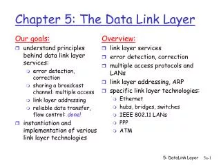
CPE 400 / 600 Computer Communication Networks. Lecture 23. Chapter 5 Link Layer. slides are modified from J. Kurose & K. Ross. Ethernet. bus topology popular through mid 90s all nodes in same collision domain (can collide with each other) today: star topology prevails

E N D
CPE 400 / 600Computer Communication Networks Lecture 23 Chapter 5Link Layer slides are modified from J. Kurose & K. Ross
Ethernet • bus topology popular through mid 90s • all nodes in same collision domain (can collide with each other) • today: star topology prevails • active switch in center • each “spoke” runs a (separate) Ethernet protocol (nodes do not collide with each other) switch bus: coaxial cable star DataLink Layer
Ethernet Frame Structure Sending adapter encapsulates IP datagram (or other network layer protocol packet) in Ethernet frame Preamble: • 7 bytes with pattern 10101010 followed by one byte with pattern 10101011 • used to synchronize receiver, sender clock rates DataLink Layer
Ethernet Frame Structure (more) • Addresses: 6 bytes • if adapter receives frame with matching destination address, or with broadcast address (eg ARP packet), it passes data in frame to network layer protocol • otherwise, adapter discards frame • Type: indicates higher layer protocol (mostly IP but others possible, e.g., Novell IPX, AppleTalk) • CRC: checked at receiver, if error is detected, frame is dropped DataLink Layer
1. NIC receives datagram from network layer, creates frame 2. If NIC senses channel idle, starts frame transmission. If NIC senses channel busy, waits until channel idle, then transmits 3. If NIC transmits entire frame without detecting another transmission, NIC is done with frame ! 4. If NIC detects another transmission while transmitting, aborts and sends jam signal 5. After aborting, NIC enters exponential backoff: after mth collision, NIC chooses K at random from {0,1,2,…,2m-1}. NIC waits K·512 bit times, returns to Step 2 Ethernet CSMA/CD algorithm DataLink Layer
CSMA/CD efficiency • Tprop = max prop delay between 2 nodes in LAN • ttrans = time to transmit max-size frame • efficiency goes to 1 • as tprop goes to 0 • as ttrans goes to infinity • better performance than ALOHA: and simple, cheap, decentralized! DataLink Layer
application transport network link physical fiber physical layer copper (twister pair) physical layer 802.3 Ethernet Standards: Link & Physical Layers • many different Ethernet standards • common MAC protocol and frame format • different speeds: 2 Mbps, 10 Mbps, 100 Mbps, 1Gbps, 10G bps • different physical layer media: fiber, cable MAC protocol and frame format 100BASE-T2 100BASE-FX 100BASE-TX 100BASE-BX 100BASE-SX 100BASE-T4 DataLink Layer
twisted pair hub Hubs … physical-layer (“dumb”) repeaters: • bits coming in one link go out all other links at same rate • all nodes connected to hub can collide with one another • no frame buffering • no CSMA/CD at hub: host NICs detect collisions DataLink Layer
Switch • link-layer device: smarter than hubs, take active role • store, forward Ethernet frames • examine incoming frame’s MAC address, selectively forward frame to one-or-more outgoing links when frame is to be forwarded on segment, uses CSMA/CD to access segment • transparent • hosts are unaware of presence of switches • plug-and-play, self-learning • switches do not need to be configured DataLink Layer
Switch: allows multiple simultaneous transmissions A • hosts have dedicated, direct connection to switch • switches buffer packets • Ethernet protocol used on each incoming link, but no collisions; full duplex • each link is its own collision domain • switching:A-to-A’ and B-to-B’ simultaneously, without collisions • not possible with dumb hub C’ B 1 2 3 6 4 5 C B’ A’ switch with six interfaces (1,2,3,4,5,6) DataLink Layer
Switch: frame filtering/forwarding When frame received: 1. record link associated with sending host 2. index switch table using MAC dest address 3. if entry found for destinationthen { if dest on segment from which frame arrivedthen drop the frame else forward the frame on interface indicated } else flood forward on all but the interface on which the frame arrived DataLink Layer
Source: A Dest: A’ A’ A MAC addr interface TTL 60 60 1 4 A A’ A A’ A A’ A A’ A A’ A A’ A A’ Self-learning, forwarding: example A • frame destination unknown: C’ B 1 2 3 flood 6 4 5 • destination A location known: C selective send B’ A’ Switch table (initially empty) DataLink Layer
S4 S3 S2 F I D H G E Interconnecting switches • switches can be connected together S1 A C B • Q: sending from A to G - how does S1 know to forward frame destined to F via S4 and S3? • A: self learning! (works exactly the same as in single-switch case!) DataLink Layer
Switches vs. Routers • both store-and-forward devices • routers: network layer devices (examine network layer headers) • switches are link layer devices • routers maintain routing tables, implement routing algorithms • switches maintain switch tables, implement filtering, learning algorithms DataLink Layer
5.5 Ethernet 5.6 Link-layer switches 5.7 Point to Point Protocol 5.8 Link Virtualization ATM MPLS Lecture 23: Outline DataLink Layer
Point to Point Data Link Control • one sender, one receiver, one link: easier than broadcast link: • no Media Access Control • no need for explicit MAC addressing • e.g., dialup link, ISDN line • popular point-to-point DLC protocols: • PPP (point-to-point protocol) • HDLC: High level data link control (Data link used to be considered “high layer” in protocol stack!) DataLink Layer
PPP Design Requirements [RFC 1557] • packet framing: encapsulation of network-layer datagram in data link frame • carry network layer data of any network layer protocol (not just IP) at same time • ability to demultiplex upwards • bit transparency: must carry any bit pattern in the data field • error detection (no correction) • connection liveness: detect, signal link failure to network layer • network layer address negotiation: endpoint can learn/configure each other’s network address DataLink Layer
PPP non-requirements • no error correction/recovery • no flow control • out of order delivery OK • no need to support multipoint links (e.g., polling) Error recovery, flow control, data re-ordering all relegated to higher layers! DataLink Layer
PPP Data Frame • Flag: delimiter (framing) • Address: does nothing (only one option) • Control: does nothing; in the future possible multiple control fields • Protocol: upper layer protocol to which frame delivered (eg, IP, PPP-LCP, IPCP, etc) • info: upper layer data being carried • check: cyclic redundancy check for error detection DataLink Layer
Byte Stuffing • “data transparency” requirement: data field must be allowed to include flag pattern <01111110> • Q: is received <01111110> data or flag? • Sender: adds (“stuffs”) special control escape <01111101> byte before each <01111110> data byte • Receiver: 01111101 : discard control escape byte, continue data reception • Q: what if data contains <01111101> ? • add extra <01111101> byte before each <01111101> data byte DataLink Layer
Byte Stuffing flag byte pattern in data to send flag byte pattern plus stuffed byte in transmitted data DataLink Layer
PPP Data Control Protocol Before exchanging network-layer data, data link peers must • configure PPP link (max. frame length, authentication) • learn/configure network layer information • for IP: carry IP Control Protocol (IPCP) msgs (protocol field: 8021) to configure/learn IP address DataLink Layer
5.5 Ethernet 5.6 Link-layer switches 5.7 Point to Point Protocol 5.8 Link Virtualization ATM MPLS Lecture 23: Outline DataLink Layer
Virtualization of networks Virtualization of resources: powerful abstraction in systems engineering: • computing examples: virtual memory, virtual devices • Virtual machines: e.g., java • IBM VM os from 1960’s/70’s • layering of abstractions: don’t sweat the details of the lower layer, only deal with lower layers abstractly DataLink Layer
The Internet: virtualizing networks … differing in: • addressing conventions • packet formats • error recovery • routing 1974: multiple unconnected nets • ARPAnet • data-over-cable networks • packet satellite network (Aloha) • packet radio network satellite net ARPAnet DataLink Layer
Internetwork layer (IP): • addressing: internetwork appears as single, uniform entity, despite underlying local network heterogeneity • network of networks The Internet: virtualizing networks Gateway: • “embed internetwork packets in local packet format or extract them” • route (at internetwork level) to next gateway gateway satellite net ARPAnet DataLink Layer
Cerf & Kahn’s Internetwork Architecture What is virtualized? • two layers of addressing: internetwork and local network • new layer (IP) makes everything homogeneous at internetwork layer • underlying local network technology • cable • satellite • telephone modem • today: ATM, MPLS … “invisible” at internetwork layer. Looks like a link layer technology to IP! DataLink Layer
ATM and MPLS • ATM, MPLS separate networks in their own right • different service models, addressing, routing from Internet • viewed by Internet as logical link connecting IP routers • just like dialup link is really part of separate network (telephone network) DataLink Layer
Asynchronous Transfer Mode: ATM • 1990’s/00 standard for high-speed (155Mbps to 622 Mbps and higher) Broadband Integrated Service Digital Network architecture • Goal:integrated, end-end transport of carry voice, video, data • meeting timing/QoS requirements of voice, video (versus Internet best-effort model) • “next generation” telephony: technical roots in telephone world • packet-switching (fixed length packets, called “cells”) using virtual circuits DataLink Layer
AAL AAL ATM ATM ATM ATM physical physical physical physical end system switch switch end system ATM architecture • adaptation layer: only at edge of ATM network • data segmentation/reassembly • roughly analagous to Internet transport layer • ATM layer: “network” layer • cell switching, routing • physical layer DataLink Layer
ATM: network or link layer? Vision: end-to-end transport: “ATM from desktop to desktop” • ATM is a network technology Reality: used to connect IP backbone routers • “IP over ATM” • ATM as switched link layer, connecting IP routers IP network ATM network DataLink Layer
AAL AAL ATM ATM ATM ATM physical physical physical physical end system switch switch end system ATM Adaptation Layer (AAL) • ATM Adaptation Layer (AAL): “adapts” upper layers (IP or native ATM applications) to ATM layer below • AAL present only in end systems, not in switches • AAL layer segment (header/trailer fields, data) fragmented across multiple ATM cells • analogy: TCP segment in many IP packets DataLink Layer
ATM Adaptation Layer (AAL) [more] • Different versions of AAL layers, depending on ATM service class: • AAL1: for CBR (Constant Bit Rate) services, e.g. circuit emulation • AAL2: for VBR (Variable Bit Rate) services, e.g., MPEG video • AAL5: for data (eg, IP datagrams) small payload -> short cell-creation delay for digitized voice User data AAL PDU ATM cell DataLink Layer
ATM Layer Service: transport cells across ATM network • analogous to IP network layer • very different services than IP network layer Guarantees ? Network Architecture Internet ATM ATM ATM ATM Service Model best effort CBR VBR ABR UBR Congestion feedback no (inferred via loss) no congestion no congestion yes no Bandwidth none constant rate guaranteed rate guaranteed minimum none Loss no yes yes no no Order no yes yes yes yes Timing no yes yes no no DataLink Layer
ATM Layer: Virtual Circuits • VC transport: cells carried on VC from source to dest • call setup, teardown for each call before data can flow • each packet carries VC identifier (not destination ID) • every switch on source-dest path maintain “state” for each passing connection • link,switch resources (bandwidth, buffers) may be allocated to VC: to get circuit-like perf. • Permanent VCs (PVCs) • long lasting connections • typically: “permanent” route between to IP routers • Switched VCs (SVC): • dynamically set up on per-call basis DataLink Layer
ATM VCs • Advantages of ATM VC approach: • QoS performance guarantee for connection mapped to VC (bandwidth, delay, delay jitter) • Drawbacks of ATM VC approach: • Inefficient support of datagram traffic • one PVC between each source/dest pair) does not scale (N*2 connections needed) • SVC introduces call setup latency, processing overhead for short lived connections DataLink Layer
ATM cell header • 5-byte ATM cell header • VCI: virtual channel ID • will change from link to link thru net • PT:Payload type (e.g. RM cell versus data cell) • CLP: Cell Loss Priority bit • CLP = 1 implies low priority cell, can be discarded if congestion • HEC: Header Error Checksum • cyclic redundancy check DataLink Layer
ATM Physical Layer • Transmission Convergence Sublayer (TCS): adapts ATM layer above to PMD sublayer below • Header checksumgeneration: 8 bits CRC • Cell delineation • With “unstructured” PMD sublayer, transmission of idle cells when no data cells to send • Physical Medium Dependent: depends on physical medium being used • SONET/SDH (like a container carrying bits): TDM OC3 = 155.52 Mbps; OC12 = 622.08 Mbps; OC48 = 2.45 Gbps, OC192 = 9.6 Gbps • T1/T3 (old telephone hierarchy): 1.5 Mbps/ 45 Mbps • unstructured: just cells (busy/idle) DataLink Layer
IP-Over-ATM IP over ATM • replace “network” (e.g., LAN segment) with ATM network • ATM addresses, IP addresses Classic IP only • 3 “networks” (e.g., LAN segments) • MAC and IP addresses ATM network Ethernet LANs Ethernet LANs DataLink Layer
app transport IP AAL ATM phy app transport IP Eth phy ATM phy ATM phy IP AAL ATM phy Eth phy IP-Over-ATM IP datagrams into ATM AAL5 PDUs IP addresses to ATM addresses DataLink Layer
Datagram Journey in IP-over-ATM Network • at Source Host: • IP layer maps between IP, ATM dest address (using ARP) • passes datagram to AAL5 • AAL5 encapsulates data, segments cells, passes to ATM layer • ATM network:moves cell along VC to destination • at Destination Host: • AAL5 reassembles cells into original datagram • if CRC OK, datagram is passed to IP DataLink Layer
Multiprotocol label switching (MPLS) • initial goal: speed up IP forwarding by using fixed length label (instead of IP address) to do forwarding • borrowing ideas from Virtual Circuit (VC) approach • but IP datagram still keeps IP address! PPP or Ethernet header IP header remainder of link-layer frame MPLS header label Exp TTL S 5 1 3 20 DataLink Layer
MPLS capable routers • a.k.a. label-switched router • forwards packets to outgoing interface based only on label value (don’t inspect IP address) • MPLS forwarding table distinct from IP forwarding tables • signaling protocol needed to set up forwarding • RSVP-TE • forwarding possible along paths that IP alone would not allow (e.g., source-specific routing) !! • use MPLS for traffic engineering • must co-exist with IP-only routers DataLink Layer
in out out label label dest interface 10 6 A 1 12 9 D 0 in out out label label dest interface in out out label label dest interface 8 6 A 0 6 - A 0 MPLS forwarding tables in out out label label dest interface 10 A 0 12 D 0 8 A 1 R4 R3 R6 0 0 D 1 1 R5 0 0 A R2 R1 DataLink Layer
principles behind data link layer services: error detection, correction sharing a broadcast channel: multiple access link layer addressing instantiation and implementation of various link layer technologies Ethernet switched LANS PPP virtualized networks as a link layer: ATM, MPLS Chapter 5: Summary DataLink Layer