Download
1 / 30
300 likes | 437 Views
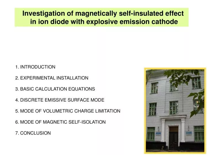
Investigation of magnetically self-insulated effect in ion diode with explosive emission cathode. INTRODUCTION EXPERIMENTAL INSTALLATION BASIC CALCULATION EQUATIONS DISCRETE EMISSIVE SURFACE MODE MODE OF VOLUMETRIC CHARGE LIMITATION MODE OF MAGNETIC SELF-ISOLATION CONCLUSION.

E N D
Investigation of magnetically self-insulated effect in ion diode with explosiveemission cathode • INTRODUCTION • EXPERIMENTAL INSTALLATION • BASIC CALCULATION EQUATIONS • DISCRETE EMISSIVE SURFACE MODE • MODE OF VOLUMETRIC CHARGE LIMITATION • MODE OF MAGNETIC SELF-ISOLATION • CONCLUSION
Principal problems of High-Power Pulsed Ion Beam formation • Generation of ion current is significantly higher than for bipolar current (Ii > IСn-L) • Formation of dense, uniform plasma at the anode (ni>1014 cm-3) • Ion beam transportation to target
электронный ток ионный ток 3
Formation of HPIB in planar diode and transportation Cathode Drift chamber Vacuum (P<10-5 Torr) Current of Charles-Langmuir for bipolar current: Ii Ie Anode Column explosion From pulsegenerator Plasma Area (S) Anode plasma Beam distribution Cathode plasma (explosive emission) U < 1 MV
Formation ofIon currentinion diode It is necessary to increase the time of electron presence (te) in the diode gap The main scheme: Virtual cathode Anode (mesh) By Cathode A A C i+ Mesh films i+ i+ e- Plasma e- +V0 +V0 Plasma Magnetically isolated diode Pinch-diode Reflective triode (double diode)
R.N. Sudan and R.V. Lovelace Generation of Intense Ion Beams in Pulsed Diodes Physical Review Letters, November 1973, vol. 31, # 19, pp. 1174- 1177
Stanley Humphries Jr. SELF MAGNETIC INSULATION OF PULSED ION DIODES Plasma Physics, 1977, Vol. 19, pp. 399 to 406. Cylindrical self magneticall insyulated ion focusing diode.
Formation of dense uniform plasma at the diode orat the anode Z U Z C A U U • Dielectric surface breakdown • Plasma-filled diode (injectionof plasma or neutral gas with consequent breakdown) • Diode with dense anode plasma formed by additional nanosecond pulse prior to the principal pulse breakdown 10 20 t, ns C U Z A U U Z 10 20 t, ns C A U Z U U Z t, ns
1. EXPERIMENTAL INSTALLATION Ion accelerator TEMP-4M Diode joint of accelerator TEMP-4M
TEMP-4M: voltage 200-300 kV Beam composition: ions of carbon (C+, C2+, C3+) and protons, ion current density on target 10-150 A/cm2 (for different types of diodes), pulse frequency 5-10 pulses per minute.
electron current density limited by space charge (Child-Langmuir law): cathode plasma expansion speed: impedance of diode: 2. BASIC CALCULATION EQUATIONS
mode of magnetic self-isolation Rexp>Rcalc discrete emissive surface mode Rexp>Rcalc mode of volumetric charge limitation Rexp=Rcalc Denotation of the operating modes of theTEMP-4M
grounded electrode (anode) potential electrode (cathode) U=- 100-150 kV Discrete explosion-emissive center 3. DISCRETE EMISSIVE SURFACE MODE
Pushkarev A.I.ets.// Technical Physics, 2008, Vol. 53, No. 3, pp. 357–362. Dependence of the duration of solid emissive surface formationon the graphite cathode surface area.
The duration of the plasma solid surface formation on the cathode is proportionate to it area. This is true for the explosion-emissive cathode in the electron diode (without magnetic field) and in the ion diode with self-magnetic insulation of electrons. Our research shows that in the discrete emissive surface mode the magnetic field influence on the plasma dynamics in the a-c gap is insignificant. • Additional articles: • Pushkarev A.I., Novoselov Yu.N., and Sazonov R.V. Efficiency of a Planar Diode with an • Explosive Emission Cathode under the Conditions of Delayed Plasma Formation • // Technical Physics, 2008, Vol. 53, No. 3, pp. 357–362. • 2. Pushkarev A.I. and Sazonov R.V. A Planar Diode Operating in the Regime of Limited Electron • Emission // Technical Physics Letters, 2008, Vol. 34, No. 4, pp. 292–295.
grounded electrode (anode) potential electrode (cathode) U=- 100-150 kV explosion-emissive plasma V = 1.3 ± 0.2 cm/μs = constant 4. MODE OF VOLUMETRIC CHARGE LIMITATION
Pushkarev A.I., Sazonov R.V. Proceeding17th Intern. Conference on High-Power Particle Beams (Beams-08) Rcalc = Rexp Carbon, Al, Cu MODE OF VOLUMETRIC CHARGE LIMITATION V = 1.3 ± 0.2 cm/μs = constant
TEMP-6 Evolution of the anode plasma expansion velocity of the self-magnetic field MID. J. P. Xin, X. P. Zhu, and M. K. Lei Initial plasma of a magnetically insulated ion diode in bipolar-pulse mode // PHYSICS OF PLASMAS 15, 123108 (2008) At PIB generation, the reduction of expansion of explosion-emissive plasma is a useful effect, which decreases the possibility of the anode-cathode gap bridging by plasma.
potential electrode (cathode) Biot-Savart-Laplace’s law grounded electrode (anode)
discrete emissive surface mode mode of volumetric charge limitation The electron drift speed in the a-c gap during the first 400-600 ns exceeds 40 mm/ns, while the electrons reach the end of the diode (electrodes length is 25 cm) within 6 ns. Therefore, the effect of magnetic insulation is insignificant.
potential electrode (anode) U=200-300 kV grounded electrode (cathode) Ion beam 5. MODE OF MAGNETIC SELF-ISOLATION
(1) (2)
potential electrode (cathode) grounded electrode (anode) discrete emissive surface mode mode of volumetric charge limitation explosion-emissive plasma The effect of plasma breakage in diode gap MODE OF MAGNETIC SELF-ISOLATION
The change of critical magnetic induction and the magnetic field induction in the gap. The change of the accelerating voltage and electron drift speed. The electron drift speed in the a-c gap during the ion beam generation is 1-4 mm/ns. The time that the electrons are in the a-c gap during the second pulse (electrodes length is 25 cm) exceeds the second pulse duration. Therefore, the effect of magnetic insulation is significant.
focusing diode S0=100 cm2 planar diode S0=100 cm2 Change of the accelerating voltage (1) and the area non-magnetized emitting surface on the focusing (2) and planar diodes (3).
CONCLUSION The analysis of the pulsed ion diode with the passive anode in the double-pulse mode showed that the influence of the magnetic self-isolation of the electrons is significant only during the ion beam generating (second pulse). The electron drift speed in the a-c gap during the first 400-600 ns exceeds 40 mm/ns,while the electrons reach the end of the diode (electrodes length is 25 cm) within 6 ns. Therefore, the effect of magnetic insulation is insignificant.
HPIB transportation to target In order to transport pulsed HPIB the neutralization of spatial positive discharge with slow electrons is required. HPIB ni ≈ ne, te = tu, Ve = KVi, K ~ 1 – 10 The energy of accompanying electrons is less than 1%
Neutralization methods of spatial positive charge in HPIB • Pulling out of electrons from the chamber walls while bombarding them by beam ions, use of special constructive elements (passive method) • Preliminary injection of plasma (pulsed plasma guns) in the area of beam distribution • Pulsed introduction of neutral gas and plasma formation due to the ion beam ionization Target Target
2. Review of High-Power Pulsed Ion accelerators Accelerators Principal part Parameters of accelerators Country, laboratory QM-1 accelerator “RHEPP-1” The magnetic pulse compressor driving a liner adder + MAP Diode (Active Anode ) (size: 4*3*2 m3) 1MV, 35 Ω, 100ns (Generator) (100 pps in the burst of 10 pulses is only for generator) USA, Sandia National Laboratories (SNL) “CHAMP” Storage capacitor + High voltage transformer + MID with plasma anode (2*2*2m3) 200 - 250 keV, 15kA, 1 mks (Ion beam) USA, Los Alamos National Laboratory (LANL) “ETIGO – II” Marx generator + DFL + TL + MID with passive anode (20*3*3,5m3) 3MV, 460kA, 50ns (Generator) 1,3 MV, 70kA (diode current), 50ns, 0,7kA/cm2 Japan, (Nagaoka,) Extremely Density Energy Research Institute (EDI) “ETIGO – IV” Storage capacitor + FL + PT + MID (4x2,5x2.5) (project) 400kV, 13kA, 120ns, 1Hz (Generator) Japan, (Nagaoka) (EDI) Harima II Marx generator + FL + Pinch diode 400 keV, 3Ω, 50ns (Generator) 180 kV, 450A/cm2, 65 ns Japan Department of Electronic Engineering, Kobe City «WERA» Marx generator + DFL + MID with active anode 600 kV, 8 Ω, 80ns(Generator) Russia,Nuclear Physics Research institute (NPI) Temp accelerators Marx generator + DFL/MDFL + MID (different type) 200 - 300 keV, 3 – 10 kA, 30 – 90 ns, (Generator) 40 – 300A/cm2 (Ion beam) Russia NPI and High Voltage Research Institute (HVRI) MUK accelerator Pulse transformer + DFL + MID 100 – 150 kV, up to 3 kA, 20* - 200 ns, metal ion Russia, WPI