Download
1 / 27
270 likes | 409 Views
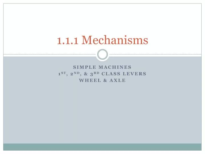
1.1.1 Mechanisms. Simple Machines 1 st , 2 nd , & 3 rd class Levers Wheel & Axle. Quietly read and decide what type of learner you may be. Once you have decided, privately write your choice on the sticky note provided. (1) I do it, build it, then I look at it to make it better.

E N D
1.1.1 Mechanisms Simple Machines 1st, 2nd, & 3rd class Levers Wheel & Axle
Quietly read and decide what type of learner you may be. Once you have decided, privately write your choice on the sticky note provided. • (1) I do it, build it, then I look at it to make it better. • (2) I need to draw/write out my ideas before I start. • (3) I work best talking about my ideas with others and make a plan before I start. • I then grouped them from their own number choice.
Your group’s challenge is to create a... • 1st class lever system • 2nd class lever system • 3rd class lever system • with various FT parts & a scientific mass. Apply the scientific mass (resistance force) to the lever and use a spring scale and/or a force meter (measures force in Newtons) to determine static equilibrium. ~OR~ • wheel & axle system • utilizing the FT parts, a scientific mass, and string. • Attach one end of a string to the outside surface of the wheel. Attach one end of a second string to the outside surface of the axle (You’ll attach the scientific mass here later)
You want me to do WHAT???? • Build a simple machine…we’ll be testing it soon for MA (AMA, IMA, and Efficiency…) • Here’s some ideas to get you started…
Hints on how these FTs go together? (You won’t use all/many of these for the simple machines, but it gives you some ideas!)
Universal Joint • Transmits power when shafts are not in line
SpurGears • Change speed, torque, and rotational speed
Idler Gear • No effect on speed and torque, but input and output shafts turn in the same direction
Rack & Pinion • Rack (in red) & pinion (in black) converts rotary motion of the pinion gear to linear motion of the rack • Reversible, positive drive with no slipping
Crown & Pinion • Mechanism reduces speed and increases torque • Output shaft is at a 90-degree angle to the input shaft • Gears rotate in opposite directions
Bevel Gears • Gears increase torque or speed • Output shaft is at a 90-degree angle to the input shaft • Gears rotate in opposite directions
Worm Gear • Gear increases torque and reduces speed • Output shaft is at a 90-degree angle to the input shaft • Direction of rotation can be reversed, but the output gear cannot drive the worm gear
Cam • As a cam rotates the flat follower is raised and lowered, converting rotary motion to linear motion FOLLOWER CAM LOBE
Chain & Sprocket • Chain and sprocket apparatus increases speed or torque • Mechanism can run in reverse direction with no slipping • Input and output shafts rotate in the same direction
Pulley & Belt • Mechanism can increase torque or speed and can run in reverse • Input and output shafts are parallel and rotate in the same direction • Slipping of the belt may occur
Motor Driven Worm Gear • Gear reduces speed and increases torque • Output shaft is at a 90-degree angle to the input shaft • Direction of motion is reversible, but the output gear cannot turn the worm gear
Motor Driven Pulley & Belt • Mechanism can increase torque or speed • Input and output shafts are parallel and rotate in the same direction • Slipping of the belt may occur
Screw • Mechanism converts rotary motion to linear motion and increases torque • Direction of rotation is reversible