Download
1 / 33
330 likes | 472 Views
The LIGO Advanced System Test Interferometer. Mike Zucker, David Shoemaker, Ken Mason LLO LSC 16 March 2001. Mission. Test LIGO components, systems at full mechanical scale Practice installation & commissioning Minimize delays & downtime for LIGO site upgrades Adv LIGO specialization:

E N D
The LIGO Advanced System Test Interferometer Mike Zucker, David Shoemaker, Ken Mason LLO LSC 16 March 2001
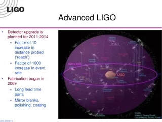
Mission • Test LIGO components, systems at full mechanical scale • Practice installation & commissioning • Minimize delays & downtime for LIGO site upgrades Adv LIGO specialization: • Test Adv LIGO seismic isolation & suspension system and associated controls at full scale • Develop detailed SEI/SUS installation & commissioning handbook • Look for unforeseen interactions & excess displacement noise • Target of opportunity: high-power tests of laser, mode cleaner • Goal: complementarity to 40m, other performance demonstrations LIGO R&D
Plan • Set up and test the infrastructure: vacuum system, optical sensing system, and data handling • Test seismic isolation systems ’stand-alone’ using seismometers • To measure relative displacement between the two seismic systems using interferometry • To test the suspensions as stand-alone elements • To assemble a Mode Cleaner suspension cavity between the two seismic isolation systems, perform tests of relative motion • To form a short Test-Mass suspension cavity on the BSC isolation system, illuminated with mode-cleaned light, perform tests of relative motion • Suspension tests to be done first for ’controls prototypes’ of the suspensions; and then for final ’noise performance prototypes’ of the suspensions. LIGO R&D
Plan • Set up and test the infrastructure: vacuum system, optical sensing system, and data handling • test seismic isolation systems ’stand-alone’ using seismometers • to measure relative displacement between the two seismic systems using interferometry • to test the suspensions as stand-alone elements • to assemble a Mode Cleaner suspension cavity between the two seismic isolation systems: tests of relative motion • to form a short Test-Mass suspension cavity on the BSC isolation system, illuminated with mode-cleaned light: tests of relative motion • Suspension tests to be done first for ’controls prototypes’ of the suspensions; and then for final ’noise performance prototypes’ of the suspensions. LIGO R&D
Controls vs. Noise suspension prototypes • Initial plan had fabrication of two complete sets of suspensions • Expensive, and poor timing w.r.t. SEI delivery • Present plan calls for fabrication of cage, sensors, actuators, upper masses and springs in ‘final design’ • Initial installation with dummy masses, steel wires • Refit with final optics and silica fibers when ready • Installation plan and practice • Initial shakedown of suspension and controls • Optics and fibers ready LIGO R&D
Design goals • Conceptual design and measurement goals consistent with the realistic aspirations for lab-scale tests of the mechanical system for the next generation LIGO • Choosing a reasonable trade of sensitivity vs. heroism • A system simple enough to succeed in the allotted time • Be at a ‘sweet spot’ for the exploitation of the installation and the manpower • Capable of being responsive to changes in the program due to (incremental) changes in suspension or isolation design, e.g., Sapphire/Silica LIGO R&D
LASTI • LIGO Vacuum Chambers • BSC, HAM • ‘L’ arrangement • 16 m baseline • Clean High Bay • Bridge Cranes • Support Labs LIGO R&D
Vacuum Layout LIGO R&D
Baseline Optical Configuration LIGO R&D
Controls Implementation LIGO R&D
Things to discuss • Thermal noise • Seismic noise • Sensing noises • Pacing from subsystems • Controls vs. noise testing • Tests beyond seismic isolation and suspensions LIGO R&D
Thermal Noise • Internal thermal noise is anticipated dominate spectrum (sapphire or silica masses) • could be frequency noise, esp. if silica test masses, of internal thermal noise of Mode Cleaner • Beam spots smaller than LIGO • leads to much greater internal thermal noise • Manageable for fused silica (~5-50x greater than Adv LIGO) • Awful for Sapphire in baseline design LIGO R&D
Fused Silica Test Mass Substrates Adv LIGO LIGO R&D
Sapphire Test Mass Substrates(g=1/3 cavity, sub-mm spots) Adv LIGO LIGO R&D
Sapphire thermal noise: Possibilities • Marginally stable cavity for larger spots • Factor 3 in spot size, ~5 reduction in noise – looks feasible, wavefront sensing signals still available • TBD if larger is sensible: models and tabletop experiments planned. • Alignment stability (and sensing) is the issue • Slightly longer cavity • BSC table is 1.5 M dia; could go from present model of 20cm to as much as 1 m – win with square root 0.2 m cavity 1 m cavity, reduced stability Adv LIGO LIGO R&D
Adv LIGO Sapphire thermal noise: Possibilities • 15 m cavity, asymmetric • Use TM – RM • Significantly lower thermal noise, but frequency noise ‘leverage’ gone • Can make two parallel cavities (sapphire-silica each), get CM rejection • Could eke out yet a bit more with lower-stability cavities (larger spots) Short cavity Long cavity, Freq noise limited Long cavity, CM rejection LIGO R&D
MC3 MC1 PSL Long Cavity Optical Configuration 16 m ETM RM ITM RM MC2 ETM, ITM: Adv LIGO LOS MCx, MMTx, SM: Adv LIGO SOS LIGO R&D
Long cavity scheme Reduces thermoelastic contribution such that we test to ~10x – 50x the Adv LIGO noise for sapphire • Increase in interferometer optical complexity • Add a second photodiode, wavefront sensing system, optical isolator; SOS-style beamsplitter and steering mirror • (Identical to old 40m configuration that demonstrated initial LIGO displacement noise) • Increase in demand on COC/SUS • Add a second Recycling Mirror and suspension, both with short (~1000 m) ROC; can be repolished to be used as Production Items • Both Test Masses can be ‘ETM Production Items’ in ROC and transmission • Does it fit? It is too heroic? LIGO R&D
Seismic noise • Seismic noise at MIT Campus site greater than sites • Stiff seismic isolation falling as ~1/f2, so similar noise at 30 Hz to LIGO • Suspension falling as 1/f8 (TM) or 1/f6 (MC); at LIGO noise by 15 Hz • For masses on a common table, common mode motion to some level (102?) LIGO R&D
Seismic noise • MIT much noisier (and variable) than sites in controls band • Also would like to have source of excitation for testing • Plan to implement the SEI hydraulic actuators • Feedforward and locally sensed feedback • Start with one hydraulic system under LIGO I HAM stack • Potential also as test of remedial retrofit for initial LIGO • Schedule TBD, but LASTI installation is ready and available • Would love to accomplish this during summer 2001 LIGO R&D
Optical sensing noise Influence scales in ratio of length of TM cavity to MC cavity (typ. 1:50) • Adv LIGO frequency noise requirement TBD (readout scheme…) • Probable ~10^-3 Hz/rHz at 10 Hz, 10^-4 at 100 Hz • limited by thermal noise of suspensions, substrates • Used in models above – looks workable • Shot Noise - want it well below thermal noise in broad frequency range; easy with LIGO I laser (~5-10 W), finesse of both cavities ~ 2000 • Radiation pressure noise - ditto on requirement; assume 10^-9 (Adv LIGO components but used at <1/10 power); no problem LIGO R&D
Tests beyond Isolation and suspension • Will study PSL, IO subsystem interface, controls, noise: • Adv LIGO mode cleaner: same length, same optics, same controls, the same environment in a practical sense; compare with second 16m cavity. Start with ~10 W • Pre-stabilized laser: install serial #1 Adv LIGO laser, test in hierarchical servo loop with mode cleaner and a test cavity • High-power testing of mode cleaner • At actual Advanced LIGO power levels, with correct suspensions and controls • Locking, and operational, tests; independent cavity noise measurement • High-power testing of test-mass suspensions • realistic photon pressure, but smaller spots – can allay fears of some controls problems • Propose to review these tests at August LSC meeting LIGO R&D
Progress on instrument equipment • PSL: thanks to LIGO I PSL team, parts largely complete • To be delivered in April, including analog and digital electronics • To be assembled by LASTI team for fun and profit • Initial test cavity built with initial LIGO SOS: thanks to LIGO I SUS team, parts largely complete • Most mechanical pieces delivered • Will re-use PNI optics • OSEMs/controllers in discussion – depends on initial LIGO and Burr-Brown • DAQ/GDS: thanks to LIGO I CDS group, configured and ordered • Racks and crates showing up • Challenge will be to assemble, configure, understand, master • Optical design: with some help from Nergis, getting going • All detailed work to be done, and better get underway soon LIGO R&D
Demands on Subsystems • Dates are ‘old’ – look critically • Seismic Isolation • one HAM in 1Q02 (parts and people arrive) • one BSC in 3Q02 (parts and people) • Suspensions • (2 LIGO I SOS like suspensions/optics for start-up tests; probably 2-4 more in 1Q02) • one MC ‘controls’ prototype (dummy masses, steel fibers) ready to install in 1Q02 (parts and people) • one TM controls prototype in 3Q02 • 3 (or maybe 4) MC ‘noise’ (fused silica fibers) in 2Q03 • 1 ITM ‘noise’ prototype in 2Q03 • 1 ETM ‘noise’ prototype in 2Q03 • 1 (or 2 if long cavities) RM ‘noise’ prototypes in 2Q03 LIGO R&D
Demands on Subsystems • Core Optics • (1” optics for ‘controls’ prototypes, 1Q02, 3Q02) • 3 MC real optics in 2Q03 • 1ETM sapphire/silica optic in 2Q03 (can be e.g., a pathfinder) • 1 ’custom’ (short radius of curvature, only good in center) ITM sapphire/silica optic in 2Q03 (or a second ‘stock’ piece if long cavities) • 1 (or 2 if long cavities) RM optic, relatively short ROC (~1km) • Laser • parts for 10 W LIGO I PSL in 1Q01 • Adv LIGO PSL in 1Q04 (complete and installed – need to discuss installed) • Input Optics support • Modulation, controls to complement Mode Cleaner by ~2Q03 LIGO R&D
Demands on Subsystems • DAQ/GDS (by 4Q01) • small-scale LIGO I system; like 40m • just disk storage • ISC (by 4Q02) • 2 (or 3 if long cavities) LIGO I length photodiodes, demod • 4 (or 6 if long cavities) quad alignment sensors, demod • subset of LIGO I controls (2 copies of LIGO I MC controls) • (controls for SUS and SEI delivered with them) • (supervisory control either LIGO I or Adv LIGO derived) LIGO R&D
Schedule • 4Qq99: LASTI envelope commissioned DONE • The vacuum envelope is installed and aligned; the vacuum pumping system is commissioned, and the system is pumped down for the first time. • 1Q00: LASTI external structures installed mostly DONE • The HAMs are installed; waiting on BSC until initial LIGO staff free • 2Q00: LASTI infrastructure design review DONE • covers noise sources; models for the performance of the system; estimates for the optical sensing system, control and data, mechanical interfaces to LASTI; and the experimental program. LIGO R&D
Schedule – to be updated during this meeting • 3Q01 ►4Q01: LASTI infrastructure complete • sensing system, control and data, and a trial cavity test of the complete system function • 1Q02: HAM pathfinder installation complete, standalone testing starts • 2Q02: MC controls SUS installation complete, testing starts • 3Q02: BSC pathfinder installation complete, standalone testing starts • 4Q02: TM controls SUS installation complete, testing starts LIGO R&D
Schedule – should not change • 3Q03: LASTI controls test review • An understanding of the controls performance of the seismic isolation systems and of the suspensions • 2Q04: LASTI noise prototype installed • The ’controls prototypes’ for suspensions changed out and fused silica fiber, sapphire test mass Test Mass suspensions installed. • 2Q05: LASTI SUS/SEI test review • The status of tests to meet the noise performance verification. • 3Q05: Adv LIGO PSL/MC tests start LIGO R&D
People • On board: Gregg Harry, Jamie Rollins, Rich Mittleman • To arrive: Joshua Phinney, add’l PostDoc • In bits and pieces: Ken Mason, Mike Zucker, David Shoemaker, add’l Electrical Engineer • Indespensible: Myron MacInnis, add’l Technician • You: the LSC LIGO R&D
General Questions • How hard to push on noise performance for sapphire test masses? • Does the system provide the infrastructure,and carry the right program for testing the • SUS • SEI • PSL • IO LIGO R&D
Random testing questions • SUS/SEI • External excitation • Safety/robustness • SEI table tilts • Optical levers • SUS • Photon actuator (technically AOS) • Thermal compensation (ditto) • Violin mode monitor(s), damping • Excitation/damping of internal mass modes • SEI • Seimisc displacements, tilts of the floor • Magnetic field mapping LIGO R&D