Download

1 / 66
660 likes | 686 Views
This lecture #3 review covers the ECG frontal plane, rate, rhythm, and normal variations in QRS axis determination. Learn the 8-step method for ECG interpretation and why determining the axis is crucial in various cardiovascular conditions.

E N D
Practical Electrocardiography- QRS Axis Determination Scott Ewing, D.O. Cardiology Fellow Lecture #3
Review • ECG Frontal Plane • Rate • Rhythm
Question • Why is the rhythm strip usually Leads II, V1, and sometimes V5?
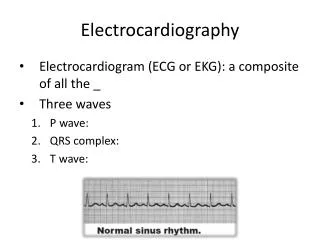
8-Step Method ECG Interpretation • Rate • Rhythm • QRS Axis • P wave • PR interval • QRS complex • QT interval • ST segment and T wave
Why Determine the Axis? • Conduction defects – left anterior and posterior fasicular block • Ventricular enlargement – left and right ventricular hypertrophy • Broad complex tachycardia – bizarre axis suggestive of ventricular origin • Congenital heart disease – atrial septal defects • Preexcited conduction – WolffParkinsonWhite syndrome • Pulmonary embolus, lateral / inferior wall MI
Artificial cardiac pacing Ascites COPD Expiration High diaphragm Hyperkalemia Inferior myocardial infarction Left anterior hemiblock Left atrial hypertrophy Left Bundle Branch Block Left ventricular hypertrophy Normal variations Ostium primum atrial septal defect (ASD) Right ventricular ectopic rhythms Tricuspid atresia Wolff-Parkinson-White Syndrome Left Axis Deviation
Anterolateral myocardial infarction Atrial Septal Defect COPD Dextrocardia Inspiration Left posterior hemiblock Left ventricular ectopic rhythms Left ventricular failure with right ventricular strain Normal variation (children, tall thin adults) Pulmonary Embolus Pulmonary Hypertension Right Bundle Branch Block Right ventricular hypertrophy Switched electrodes Ventricular Septal Defect (VSD) Wolff-Parkinson-White Syndrome Right Axis Deviation
Artificial cardiac pacing COPD Hyperkalemia Lead transposition Ventricular tachycardia Extreme Axis Deviation
QRS Complex • QRS Axis • Represents direction of the mean QRS vector in the frontal plane • Determined using hexaxial reference system derived from the Einthoven equilateral triangle
QRS Complex • Normal QRS axis is -30° to 100° • Axis is usually shifted leftward with age • In individuals < 30, axis is seldom superior to 0° (normal 0° to 100°) • In individuals > 40, axis is seldom to right of 90° (normal -30° to 90°)
QRS Complex • There is an association between QRS axis and body weight • Thinner persons tend to have more vertical axes (toward 90°, or rightward) • Obese persons tend to have more horizontal axes (toward 0°, or leftward) • There is no significant gender difference in the axis
ECG Axis • Frontal plane leads are represented on a hexaxial diagram • Positive pole of each lead axis (solid line) and negative pole (hatched line) are designated by their angular position relative to the positive pole of lead I (0°) • Mean electrical axis of the QRS complex is measured with respect to this display
aVR aVL I III II aVF QRS Axis Determination • Lead orientation • Normal axis -30° to 100°
QRS Axis Determination- Approach • 1st Method (Quick) • Is it normal? • 2nd Method • Use algebraic sum of the deflections in 2 leads, usually I and aVF • Plot out axis • 3rd Method • Find lead with isoelectric complex • QRS is perpendicular to this lead, with positive terminus pointing toward lead with largest net positive deflection
aVR aVL I III II aVF QRS Axis Determination- Quick Method • Lead I lies at 0° • If the QRS in Lead I is mainly positive (even if only slightly) it means the axis will be anywhere between -90° to 90° • Now, look at Lead II
aVR aVL I III II aVF QRS Axis Determination- Quick Method • Lead II lies at 60° • If the QRS in Lead II is mainly positive (even if only slightly) then the axis can be anywhere between -30° to 150°
aVR aVL I III II aVF QRS Axis Determination- Quick Method • If Lead I is positive the axis is between -90° and 90° • If Lead II is positive the axis is between -30° and 150° • Combined, the axis must lie between -30° and 90°
QRS Axis Determination- Approach • 1st Method (Quick) • Is it normal? • 2nd Method • Use algebraic sum of the deflections in 2 leads, usually I and aVF • Plot out axis • 3rd Method • Find lead with isoelectric complex • QRS is perpendicular to this lead, with positive terminus pointing toward lead with largest net positive deflection
-30° 0° - Lead I 100° 90° - Lead aVF QRS Axis Determination- Using Leads I and aVF
QRS Axis Determination- Case #1 • Lead I corresponds to the x-axis • Sum the total positive and negative deflection • 8 mm in this case Lead I
QRS Axis Determination- Case #1 • Lead aVF corresponds to the y-axis • Sum the total positive and negative deflection • 9 mm in this case Lead aVF
-30° 0° - Lead I 100° 90° - Lead aVF QRS Axis Determination– Case #1 Plot Results
QRS Axis Determination- Case #2 • Lead I corresponds to the x-axis • Sum the total positive and negative deflection • 9 – 5 = 4 mm in this case Lead I
QRS Axis Determination- Case #2 • Lead aVF corresponds to the y-axis • Sum the total positive and negative deflection • 4 - 2 = 2 mm in this case Lead aVF
-30° 0° - Lead I 100° 90° - Lead aVF QRS Axis Determination– Case #2 Plot Results
QRS Axis Determination- Case #3 • Lead I corresponds to the x-axis • Sum the total positive and negative deflection • 6 mm in this case Lead I
QRS Axis Determination- Case #3 • Lead aVF corresponds to the y-axis • Sum the total positive and negative deflection • 0 - 7 = -7 mm in this case Lead aVF
-30° 0° - Lead I 100° 90° - Lead aVF QRS Axis Determination– Case #3 Plot Results
QRS Axis Determination- Using Leads I and III -30° 0° - Lead I 120° - Lead III 100°
QRS Axis Determination • Lead I corresponds to the x-axis • Sum the total positive and negative deflection • 6 mm in this case Lead I
QRS Axis Determination • Lead III corresponds to the y-axis • Sum the total positive and negative deflection • 0 - 11 = -11 mm in this case Lead III
-30° 0° - Lead I 120° - Lead III 100° QRS Axis Determination- Using Leads I and III
QRS Axis Determination- Approach • 1st Method (Quick) • Is it normal? • 2nd Method • Use algebraic sum of the deflections in 2 leads, usually I and aVF • Plot out axis • 3rd Method • Find lead with isoelectric complex • QRS is perpendicular to this lead, with positive terminus pointing toward lead with largest net positive deflection
QRS Axis Determination • Find the isoelectric lead if there is one (i.e. the lead with equal forces in the positive and negative direction) • Often this is the lead with the smallest QRS • QRS axis is perpendicular to that lead's orientation • Since there are two perpendiculars to each isoelectric lead, choose the perpendicular that best fits the direction of the other ECG leads • If there is no isoelectric lead, there are usually two leads that are nearly isoelectric and these are always 30° apart • Find the perpendiculars for each lead and choose an approximate QRS axis within the 30° range
aVR aVL I III II aVF QRS Axis Determination- Using Isoelectric Lead