Download
1 / 29
290 likes | 418 Views
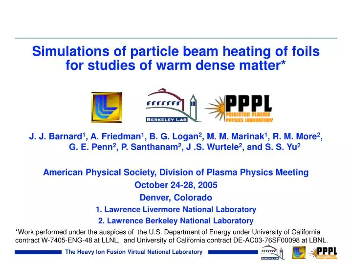
Simulations of particle beam heating of foils for studies of warm dense matter*. J. J. Barnard 1 , A. Friedman 1 , B. G. Logan 2 , M. M. Marinak 1 , R. M. More 2 , G. E. Penn 2 , P. Santhanam 2 , J .S. Wurtele 2 , and S. S. Yu 2

E N D
Simulations of particle beam heating of foils for studies of warm dense matter* J. J. Barnard1, A. Friedman1, B. G. Logan2, M. M. Marinak1, R. M. More2, G. E. Penn2, P. Santhanam2, J .S. Wurtele2, and S. S. Yu2 American Physical Society, Division of Plasma Physics Meeting October 24-28, 2005 Denver, Colorado 1. Lawrence Livermore National Laboratory 2. Lawrence Berkeley National Laboratory *Work performed under the auspices of the U.S. Department of Energy under University of California contract W-7405-ENG-48 at LLNL, and University of California contract DE-AC03-76SF00098 at LBNL.
Abstract We present simulations of particle beam heating of target foils using the multi-physics radiation hydrodynamics code HYDRA**. We simulate possible targets for a near-term experiment at LBNL (the so-called Neutralized Drift Compression Experiment, NDCX) and possible later experiments on a proposed facility (NDCX-II) for studies of warm dense matter. Simulation results are presented showing the degree of temperature uniformity and the maximum temperature expected. Various target materials (including aluminum, aluminum foam, water ice, and gas jets) and target configurations are presented. Strategies for characterizing the material equation of state, using data from the experiments together with simulations, will be discussed. Requirements on the NDCX-II accelerator, based on target considerations, will also be discussed. **M. M. Marinak, G. D. Kerbel, N. A. Gentile, O. Jones, D. Munro, S. Pollaine, T. R. Dittrich, and S. W. Haan, Phys. Plasmas 8, 2275 (2001).
Outline of poster 1. Motivation for accelerator driven Warm Dense Matter studies 2. Parameters of current and proposed accelerators 3. Simulations of target experiments -- Validation of uniformity -- Explorations of two-phase regime Existence of temperature/density “plateaus” -- Rayleigh-Taylor instability using ion deposition -- Other experiments
The r - T regime accessible by beam driven experiments lies square in the interiors of gas planets and low mass stars Figure adapted from “Frontiers in HEDP: the X-Games of Contemporary Science:” Accessible region using beams in near term Region is part of Warm Dense Matter (WDM) regime WDM lies at crossroads of degenerate vs. classical and strongly coupled vs. weakly coupled Terrestial planet
Strategy: maximize uniformity and the efficient use of beam energy by placing center of foil at Bragg peak In simplest example, target is a foil of solid or “foam” metal fractional energy loss can be high and uniformity also high if operate at Bragg peak (Larry Grisham, PPPL) Ion beam Example: Ne Energy loss rate DdE/dX DT In example, Eentrance=1.0 MeV/amu Epeak= 0.6 MeV/amu Eexit = 0.4 MeV/amu (DdE/dX)/(dE/dX) ≈ 0.05 (MeV/mg cm2) Enter foil Exit foil (dEdX figure from L.C Northcliffe and R.F.Schilling, Nuclear Data Tables, A7, 233 (1970)) Energy/Ion mass (MeV/amu)
Pulse duration must be short to avoid hydrodynamic expansion and cooling tpulse < zr/cs Here: tpulse = pulse duration zr = distance, such that diagnosable portion of heated target remains cs = sound speed r zr≈cst cs ≈2cst Dz z Rarefaction wave propagates inward at cs (with csincreasing with time) The heating pulse should be delivered in a time short compared to the time it takes for a rarefaction wave to reach an interior point, such that a significant portion of the target has reached maximum temperature.
Basic Requirements Temperature T > ~ 1 eV to study Warm Dense Matter regime Mass Density r ~ 0.01 to 1.0 times solid density Strong coupling constant G ~ 1 For isochoric heating: Dt must be short enough to avoid cooling from hydrodynamic expansion Uniformity: DT/T < ~5% (to distinguish various equations of state) Low accelerator cost is a strong consideration, in present environment
A user facility for ion beam driven HEDP will have unique characteristics Precise control of energy deposition Uniformity of energy deposition Large sample sizes compared to diagnostic resolution volumes Relatively long times allow equilibrium conditions A benign environment for diagnostics High shot rates (10/hour to 1/second) (simple targets and high accelerator rep rates)
Various ion masses and energies have been considered for Bragg-peak heating Beam parameters needed to create a 10 eV plasma in 10% solid aluminum foam, for various ions (10 eV is equivalent to ~ 1011 J/m3 in 10% solid aluminum)
kT= 10.0 eV 3.0 1.0 0.3 0.1 Total charge (mC) 0.03 0.01 The parameters for a Neutralized Drift Compression Experiment (NDCX II) are chosen to heat target to reach WDM conditions Target requirements set specifications for beam phase space at end of accelerator (and hence at injector) • Longitudinal velocity spread limits pulse duration • Emittance and chromatic aberrations limit spot radius • Large velocity tilt allows shorter pulses but adds to chromatic aberration Na Z=11; A=22.99 Ecenter of foil= 15.7 MeV Efoil entrance = 23.5 MeV (b =0.047) dE/dX = 10.13 MeV cm2/mg Z = 5.75 m (ral/r) U= 8.7 x 10¹⁰ J/m3 (1mm/r)2 (qtot/0.1mC)(r/ral) kT= 1.5 eV (1mm/r)2(qtot/0.1mC) Tradeoffs for compression factor of 20 and 1 mm final spot radius: Without adiabatic lens: Dv/v_tilt= 0.05 eN <= 2.3 mm-mrad dp/p_rms = 0.2 % (at 1 MV, 177 ns injector)
Parameters of experiments in the NDC sequence leading to a user facility (IBX/NDC) Existing machine, 1 year goal 3 - 5 year goal 10 year goal NDCX = neutralized drift compression experiment IBX = integrated beam experiment
We have begun using the 3D LLNL code HYDRA for our target studies • - A state-of-the-art multi-physics radiation transport/ hydrodynamics code by M. Marinak et al1 • - Initial explorations of ion beam interactions with foil targets2: 20 MeV Ne beam hitting 10% Al foam foil Power vs. time: Power vs. radius: 1 ns 1 mm Illustrative example of non-uniform heating: Temperature contour plot T t=3.0 ns T t=0 T t=1.0 ns (end of current pulse) T t=2.0 ns Ion beam (1 mm radius) Initial foam foil keV r r=rb r=0 (2D [r-z], time-dependent simulations; Intensity 100 x higher, foil 3 x thicker for demo only) 1. M. M. Marinak, G. D. Kerbel, N. A. Gentile, O. Jones, D. Munro, S. Pollaine, T. R. Dittrich, and S. W. Haan, Phys. Plasmas 8, 2275 (2001). 2. Simulation collaborators: J.J. Barnard, G.E. Penn, J. S. Wurtele, P. Santhanam, A. Friedman, M. M. Marinak
0.1 solid Al eV 0.01 solid Al (at t=2.2 ns) Initial Hydra simulations confirm temperature uniformity of targets at 0.1 and 0.01 times solid density of Aluminum time (ns) 0 Dz = 48 m r =1 mm 0.7 1.0 Axis of symmetry 1.2 2.0 0 r 1 mm eV Dz = 480 m 2.2 (simulations are for 0.3 mC, 20 MeV Ne beam -- IBX/NDC parameters from workshop).
For NDCX-II parameters, temperatures of a few eV could be achieved with high uniformity t=1ns Variation of target temperature with total beam charge Q 3 DT/T = .037 2 T (eV) 1 initial foil width = 57 m Q=0.1mC (HYDRA results using QEOS, in Al 10% solid density; 23.5 MeV 1 mm Na+ ion beam) -100 0 100 z(m)
New theoretical EOS work meshes well with experimental capabilities we will be creating Plot of contours of fractional pressure difference for two common EOS (R. Lee) Large uncertainties in WDM region in and near the 2-phase (liquid-vapor) region Getting two-phase regime correct will be a main job for WDM R. More recently developed a new theoretical EOS for Sn. Interesting exactly in the ~1.0 eV regime. New EOS (More, Kato, Yoneda, 2005 preprint.) P (J/cm3) Critical point is now unknown for many metals, such as Sn r (g/cm3) T (eV) EOS tools for this temperature - density range are now being developed.
1.2 Temperature 0 -3 0 New EOS predicts a sharp density cliff which may facilitate detection and help determine metallic critical points R. More et al1 have used the new EOS in 1D hydro calculations. EOS based on known energy levels and Saha equation More accurate than QEOS “average” (Thomas Fermi) atom model Expansion into 2-phase region leads to r-T plateaus with sharp edges1,2 Initial distribution Exact analytic hydro (using numerical EOS) Numerical hydro +++++++++ 8 (g/cm3) T (eV) Density 0 0 -3 z(m) z(m) Example shown here is initialized at T=0.5 or 1.0 eV and shown at 0.5 ns after “heating.” Expect phenomena to persist for longer times and distances, but still to be explored. 1More, Kato, Yoneda, 2005, preprint. 2Sokolowski-Tinten et al, PRL 81, 224 (1998)
HYDRA simulations show both similarities to and differences with More, Kato, Yoneda simulation of 0.5 and 1.0 eV Sn at 0.5 ns (oscillations at phase transition at 1 eV may be due to numerical problems, probably triggered by the different EOS physics of matter in the two-phase regime) Propagation distance of sharp interface is approximately correct Density Temperature T0 = 0.5 eV T0 = 0.5 eV Temperature Density Density oscillation likely caused by ∂P/∂r instabilities T0 = 1 eV T0 = 1 eV
0.754 0.646 0.554 0.476 0.408 0.350 0.300 0.257 0.221 Differences between HYDRA and More, Kato, Yoneda simulations are likely due to differences in EOS Critical point 10000 3.00 eV 2.57 2.21 1.89 1.62 1.39 1.19 1.02 0.879 T= 3.00 eV 2.25 1.69 1.26 0.947 0.709 0.531 0.398 0.298 0.224 1000 T= 100 10 Pressure (J/cm3) 1 eV 1 1 eV 0.1 0.01 Density (g/cm3) In two phase region, pressure is independent of average density. Material is a combination of liquid and vapor (i.e. bubbles). Microscopic densities are at the extreme ends of the constant pressure segment. Hydra used modified QEOS data as one of its options. Negative ∂P/∂r (at fixed T) results in dynamically unstable material. EOS should be described by 2-phase Maxwell construction.
Early explorations using Hydra of beam heating of Sn at solid density to ~1 eV shows evidence of T plateau 7 0.5 ns At 0.5 ns, T = 1.2 eV T (eV) Q=0.03 mC r (g/cm3) 1.0 z (m) 0 2 z (m) 0 2 1.0 ns At 1.0 ns T=1.4 (and 0.95 eV) T (eV) r (g/cm3) 1.0 z (m) 0 2 z (m) 0 2
0 2 0 2 0 2 z(m) z(m) z(m) Variation of temperature profiles for 2 m Sn foil with various beam intensities, shows hints of predicted behavior All plots are for 23.5 Na beam, after 1 ns Q=0.03 mC Tcenter=0.9 eV Tplateau=0.5 eV Q=0.008 mC Tcenter=0.6 eV Tplateau=0.25 eV Q=0.015 mC Tcenter=0.9 eV Tplateau=0.5 eV T (eV) 1 Existence of temperature plateaus appears related to passage of matter through 2-phase medium, but density plateaus not present, perhaps due to finite beam duration or differences in EOS
We have used HYDRA to begin scoping possible near-term experiments on NDCX-I 2 ns (end heating) 11 ns 120 ns 690 ns Beam Max. Temp: 0.1 eV 1 mm Gas “jet” Axis of Sym-metry 2 mm Temperature Contours Simulation parameters: Target: 1 mm thick Argon gas “jet” at 1 atmosphere Beam: 0.5 mm radius, 2 ns, 1A, K+ (final strong solenoid would be required for 0.5 mm spot) eV
Other near-term hydro experiments could be carried out with a frozen liquid (such as H20, iodine, mercury, etc.) Beam parameters: 0.5 mm radius 1 A K+ 2 ns Beam 10 m thick layer of ice t = 0 ns 2 ns (end of heating) 1 mm Target parameters: 10 m thick layer of water ice (possibly on top of solid surface--not included in simulation) 5 ns Maximums: T = 0.07 eV P=0.027 Mbar = 2.7GPa (at 3 ns) 9 ns
beam (1.8 mm radius) Target experiments on ETA II, could also provide target experience in interesting regime • Example: “Tantalum-like” foil, with equivalent 40 GeV proton beam t = 241 ns t=71 ns (end of heating) Density Density 0.25 mm thick “Ta” foil 1 eV r=0 r=rb Temperature Temperature t=0 t=71 ns t=241 ns Temperature • - ETA II parameters: 5 MeV e-, 2 kA, 50 ns, • Need to adapt electron beam deposition to include scattering ETA-II
Beam Target foil (near the end of the heating pulse) Energy deposition using ion beams may alter the growth rate of the Rayleigh-Taylor instability relative to lasers Beam Ablation blowoff layer Target foil (with initial density modulation) a Since dense regions absorb more energy, growth rate may be altered using ion depositiion relative to lasers Growth rateg (for laser deposition): g ≈ (k a /( 1 + k L))1/2 - a k Va, wherekis the wave number of the perturbation,ais the acceleration rate,Lis the density-gradient scale length, ais a constant between 1 and 3, Vais the velocity of the ablation front (Lindl, 19981) 1. John D. Lindl,"Inertial Confinement Fusion," Springer-Verlag, NY, 1998
We have begun using Hydra to explore accelerator requirements to study beam driven Rayleigh Taylor instability r t= 0.4 ns r t= 1 ns r t= 5 ns r t= 10 ns Beam g/cm3 T t= 10 ns T t= 0.4 ns T t= 1 ns T t= 5 ns eV 23 MeV Ne, 0.1 mC, 1 ns pulse (NDCX II) impinges on 100 m thick solid H, T=0.0012eV, r =0.088 g/cm3; No density ripple on surface, blowoff accelerates slab
When initial surface ripple is applied, evidence for Rayleigh Taylor instability is suggestive r t=0.4 ns r t=1 ns r t=3.5 ns r t=5 ns r t=7.5 ns r t=10 ns T t=0.4 ns T t=1 ns T t=3.5 ns T t=5 ns T t=7.5 ns T t=10 ns
When initial surface ripple is applied, evidence for Rayleigh Taylor instability is suggestive (-- continued) vz t=10 ns vz t=5 ns vz t=1 ns vz t=7.5 ns vz t=0.4 ns vz t=3.5 ns Scales from previous page (r and T): Scale for above figures (vz): cm/ms g/cm3 eV
We have begun establishing target requirements for WDM studies and translating to requirements on the accelerator We are quantitatively exploring the tradeoffs involved in focusing the beam in both space and time We are using a state-of-the-art rad-hydro(HYDRA) simulation code to evaluate targets for WDM study. We are also comparing HYDRA with lower-dimensional codes, but using advanced EOS models Several potential experiments are being considered including: -- EOS/conductivity experiments on ETA-II -- NDCX-I experiments heating condensed ices -- Two-phase experiments on NDCX-II, IBX/NDC -- Rayleigh-Taylor experiments on NDCX-II, IBX/NDC Future simulations and calculations will simulate in detail many of these potential experiments