Download
1 / 53
630 likes | 1.01k Views
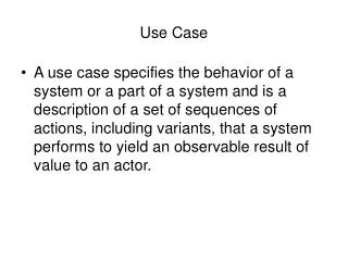
Use-Case Analysis. Analyze the requirements to discover what the system objects are These slides capture the use-case analysis activity of the Rational Unified Process. Use-Case Analysis. Use-case analysis is where the requirements meet object-orientation

E N D
Use-Case Analysis Analyze the requirements to discover what the system objects are These slides capture the use-case analysis activity of the Rational Unified Process
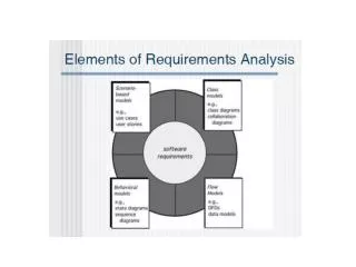
Use-Case Analysis • Use-case analysis is where the requirements meet object-orientation • Recall: in the Unified Process, the use-case model is the primary artifact in the requirements model • In use-case analysis, identify the classes which perform a use-case flow of events • Distribute the use-case behavior to those classes • Identifying the responsibility of the classes • Develop use case realizations that model the collaborations between instances of the identified classes • How the class instances work together to deliver the requirements • The result is a first-draft, rough-cut of the system object model • An abstraction of the design model; refined during design
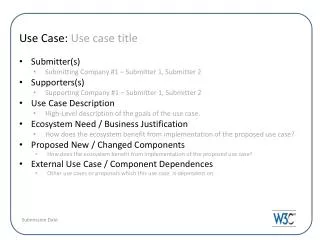
Review: Use-Case Realization • A use-case realization is a description of how a particular use case is realized within the design model, in terms of collaborating objects • It is one possible realization, corresponding to a specific selection among design options Use Case Use-Case Realization Class diagram Use Cases Sequence diagrams <<trace>> Use Case Specification Communication diagrams
Software Architecture Document (Use-case View) Glossary Analysis Classes Supplementary Specification Use-Case Realization (Identified) Analysis Model (Updated) Use-Case Analysis Instantiate the activity once per use case Use-Case Realization (Preliminary) Use-Case Analysis Use-Case Model
Use-Case Analysis - Steps • Supplement the Use-Case Description • For each use-case realization • Find classes from use-case behavior • Distribute use-case behavior to classes • For each resulting analysis class • Describe responsibilities • Describe attributes and associations • Qualify architectural analysis mechanisms • Unify analysis classes • Checkpoints
Use-Case Analysis - Steps Next • Supplement the Use-Case Description • For each use-case realization • Find classes from use-case behavior • Distribute use-case behavior to classes • For each resulting analysis class • Describe responsibilities • Describe attributes and associations • Qualify architectural analysis mechanisms • Unify analysis classes • Checkpoints
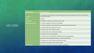
Use-Case Specification Supplemented Use-Case Specification Supplement the Use-Case Description • Capture additional information needed in order to understand the required internal behavior of the system that may be missing from the use-case description written for the customer of the system. • Note: exposes some solution structure – not appropriate for requirements, but necessary to define objects. The system displays a list of course offerings. The system retrieves a list of course offerings from the course catalog legacy database. The system displays the course offerings.
Use-Case Analysis - Steps • Supplement the Use-Case Description • For each use-case realization • Find classes from use-case behavior • Distribute use-case behavior to classes • For each resulting analysis class • Describe responsibilities • Describe attributes and associations • Qualify architectural analysis mechanisms • Unify analysis classes • Checkpoints Next
Analysis Classes: A First Step Towards Executables Use-Cases Analysis Classes Design Elements Source Code Executables Use-Case Analysis
The Analysis Model is Temporary • The analysis model is an early conceptual model of how the system will work • It evolves quickly • It is fluid, changing as different representations and their implications are explored • Analysis classes rarely survive into design unchanged • A given analysis class often represents collaborations of multiple design objects, encapsulated by subsystems • Think of analysis classes as “proto-classes” representing “clumps of behavior” • Allow us to explore alternative distribution of responsibilities to achieve a good separation of concerns • Be careful to not spend too much time on “formal” documentation and a well-polished model • Consider the analysis model as informal • “Structured doodling”, artist “studies”
Use-Case Specification Find Classes from Use-Case Behavior • The complete behavior of a use-case must be allocated to analysis classes
Boundary Control Entity Class Stereotypes for Analysis • Distinguish and separate the concerns of system interface from application logic/control flow from persistent application objects • Specialize the class object in UML to represent the distinctions • Entity classes: system information • Long-lived, real-life object or event in the application domain • Data and behavior • Usually persistent (saved in a file or database) • Boundary classes: system boundary • Interaction between the system and its actors • At the system boundary • Control classes: use-case behavior coordination • Coordination and sequencing of system behavior • Transactions
Analysis Classes • The distinction into the three analysis class types helps • Clarify and separate class roles in the system • Separate things that tend to change separately • Classes identified in analysis need not have a stereotype • Once the roles have been analyzed and there is a good system decomposition, the distinction between types is no longer really useful • The distinction (and the stereotypes) tend to go away in design
Alternate Visualizations of the Same Thing <<boundary>> • UML allows multiple graphical representations (“syntax”) of the same conceptual (semantic) model element Boundary Boundary Boundary <<control>> Control Control Control <<entity>> Entity Entity Entity
Boundary Classes • A boundary class intermediates between the system and something outside the system • Insulate the system from changes in the surroundings (changes in external systems, user requirements, etc.) • Types • User interface classes • Display windows/screens, keyboard, microphone voice recognition, motion tracker, etc. • System interface classes • Interface to external systems, legacy systems, use of an external Application Programming Interface (API) • Device interface classes • Interface to devices which detect external events • Capture the responsibilities of a device or sensor
Boundary Boundary Boundary Control Entity Use Case <<actor>> The Role of Boundary Classes External System Actor • Model interaction between the system’s surroundings and its inner workings • Transform and translate events • Note changes in the system presentation (such as a user interface display) • Make it easier to understand and clarify system boundaries • Help identify related services • For example, identifying a printer interface suggests the need to format printouts • Insulate external forces from system inner workings and vice-versa • For example, changing a communication protocol or GUI look-and-feel should mean only changing the boundary classes, not the entity and control classes Entity
RegisterForCoursesForm CourseCatalogSystem <<actor>> Course catalog system Finding Boundary Classes Register For Courses Student • Guideline: Start with one boundary class per actor/use-case pair • Concentrate on the responsibilities (NOT the details) • User interface classes • Concentrate on what information is presented (NOT on the UI details of graphics, layout, style, controls, etc.) • System and device interface classes • Concentrate on what protocols must be defined (NOT on how the protocols will be implemented) – responsibilities, not details • If there is already a working communication with the external system or device, make note of it for later reference during design • Consider the source of all external events and make sure there is a way for the system to detect these events
Entity Classes • Entity objects represent the key concepts of the system being developed • Store and manage information in the system • Data (usually persistent) • Structure (usually persistent) • Behavior • Usually not specific to one use-case • Examples • Banking: Account, Customer • Network Management: Node, Link • Information the system needs to know about its actors • A surrogate for the actor – the actor itself is separate • Identify the entity classes by name and brief description
Finding Entity Classes Different! Consider “StudentInfo” or “StudentActor” as names to clarify the distinction • Sources • Glossary, business/domain model, use-case flow of events, key abstractions (from architectural analysis) • A technique: study the nouns • Underline noun clauses in the use-case flow of events • Remove redundant candidates • Remove vague candidates (or make them clear) • Remove actors (out of scope, but they may have surrogate entity classes) • Remove implementation constructs • Remove attributes (save for later) • Remove operations
<<actor>> Course catalog system Control Classes Register For Courses Student • Use-case behavior coordinator • Typically, one control class per use case • Create control object at start of use-case, delete it at end • Delegates actor-visible behavior to the entity classes • “Orchestrate and Delegate Behavior” • If the use-case is simply accessing and changing information, a control class may be unnecessary (boundary classes and entity classes interact directly) • Examples • Transaction management • Resource coordination • Error handling • Decision logic (control the flow of events; state-dependent flows) • May disappear in design – become methods on UI classes • “On MouseEvent do X” RegistrationController
RegisterForCoursesForm CourseCatalogSystem Analysis Classes for “Register for Courses” External system Register For Courses Course catalog system Student Requirements (Use-Case) Model Analysis Model – View of Participating Classes in Use-Case Realization Register for Courses External system RegistrationController Course catalog system Student Student Schedule CourseOffering
Use-Case Analysis - Steps • Supplement the Use-Case Description • For each use-case realization • Find classes from use-case behavior • Distribute use-case behavior to classes • For each resulting analysis class • Describe responsibilities • Describe attributes and associations • Qualify architectural analysis mechanisms • Unify analysis classes • Checkpoints Next
Distribute Use-Case Behavior to Classes • For each use-case flow of events • Identify participating analysis classes • Allocate use-case responsibilities to those analysis classes • Model analysis class interactions in interaction diagrams • One interaction diagram for each variant of a use-case’s flow of events • Flows for different user options • Exception-handling flows • etc. • In analysis, collaboration diagrams (as opposed to sequence diagrams) help focus on class responsibilities • Even so, I tend to use sequence diagrams to capture details and trace flow of control
Guidelines: Allocating Responsibilities to Classes • Use analysis class stereotypes as a guide • Boundary classes • Behavior that involves communication with an actor • Entity classes • Behavior that involves the data encapsulated within the abstraction • Control classes • Behavior specific to a use case or part of a very important flow of events (continued)
Guidelines: Allocating Responsibilities to Classes(continued) • Who has the data needed to perform the responsibility? • If one class has the data, put the responsibility with the data • If multiple classes have the data • Put the responsibility with one class and add a relationship to the other • Create a new class, put the responsibility on the new class, and add relationships to classes needed to perform the responsibility • Put the responsibility on the control class, and add relationships to classes needed to perform the responsibility • Keep clear the responsibility: one object’s need to know information is not the same as an object’s responsibility to provide information and manage information: client vs. supplier • Refactor • Re-allocate data and responsibility among classes • Reuse: Assign new responsibility to a class that has similar responsibility
The classes Client Sequence Diagrams Supplier PerformResponsibility() Client object Supplier object PerformAnotherResponsibility() Object Lifeline : Client : Supplier Reflexive message (Message to self) 1. PerformResponsibility 1.1. PerformAnotherResponsibility Sample Script Message Hierarchical message numbering Script Focus of Control (Activation)
Build a Sequence Diagram for “Register for Courses” Basic flow, top level (The basic flow has six diagrams capturing different portions of the flow)
Build a Sequence Diagram for “Register for Courses” Basic flow, create a schedule portion
Collaboration Diagrams Message 1.1. PerformAnotherResponsibility 1. PerformResponsibility : Client : Supplier Client object Link Supplier object Note: A common mistake is to associate the behavior with the client, instead of the supplier. Even though the client initiates the behavior and needs it done, it is the supplier that is responsible for carrying out the behavior at the client’s request.
Collaboration Diagram for “Register for Courses” Basic flow, create a schedule portion Compare this to the equivalent sequence diagram, earlier. Which visualization makes which design aspects clearer? 5: // display course offerings( ) 6: // display blank schedule( ) 1: // create schedule( ) 7: // select 4 primary and 2 alternate offerings( ) : RegisterForCoursesForm 2: // get course offerings( ) 8: // create schedule with offerings( ) : Course Catalog 4: // get course offerings( ) : Student 3: // get course offerings() : RegistrationController : CourseCatalogSystem 9: // create with offerings( ) 10: // add schedule(Schedule) : Student : Schedule
Collaboration Diagrams Show relationships (i.e., structure) in addition to interactions Better for visualizing patterns of collaboration Better for visualizing all of the effects on a given object Easier to use for brainstorming sessions CRC (Class, Responsibility, Collaboration) cards Sequence Diagrams Show the explicit sequence of messages Better for visualizing overall flow of control Better for real-time specifications and for complex scenarios Collaboration Diagrams vs. Sequence Diagrams
Use-Case Analysis - Steps • Supplement the Use-Case Description • For each use-case realization • Find classes from use-case behavior • Distribute use-case behavior to classes • For each resulting analysis class • Describe responsibilities • Describe attributes and associations • Qualify architectural analysis mechanisms • Unify analysis classes • Checkpoints Next
// PerformAnotherResponsibility Describe Responsibilities // PerformResponsibility : Client : Supplier • A responsibility is a statement of something an object can be asked to provide • Actions the object can perform on request • Knowledge the object maintains and provides to other objects • Messages on interaction diagrams define responsibilities • Responsibilities evolve into one or more operations on classes in design • Document responsibilities in one of two ways • As “analysis” operations • Class operations with “//” pre-pended as a naming convention • As textual description of the analysis class Supplier // PerformResponsibility // PerformAnotherResponsibility
“Register for Courses” Realization View of Participating Classes (VOPC) Show only those classes, attributes, operations, and associations involved in realizing this use case
Maintaining Consistency: What to Look For • In order of criticality: • Redundant responsibilities across classes • Disjoint responsibilities within classes • Class with one responsibility • Class with no responsibilities • Better distribution of behavior • Class that interacts with many other classes • A class does everything about X, and only things about X • Decompose; separate concerns • Integrate; combine all aspects of a single concern • Update the interaction diagrams to reflect the re-factored classes
Use-Case Analysis - Steps • Supplement the use-case description • For each use-case realization • Find classes from use-case behavior • Distribute use-case behavior to classes • For each resulting analysis class • Describe responsibilities • Describe attributes and associations • Define attributes • Establish associations between analysis classes • Describe event dependencies between analysis classes • Qualify architectural analysis mechanisms • Unify analysis classes • Checkpoints Next
CourseOffering courseNumber : String startTime : Time endTime : Time days : Enumeration numStudents : Integer Notation <<stereotype>> ClassName Review: Attributes - PrivateAttribute : Type = InitialValue + PublicAttribute : Type = InitialValue # ProtectedAttribute : Type = InitialValue • Attributes store information • Atomic • No responsibilities • Attribute name should clearly state what information the attribute holds • Supplement with attribute description, where the name is not sufficient • During analysis, attribute types should be from the domain, not from the programming language • In analysis, don’t worry too much about attribute types/signatures • But do look for types that should be new classes <<entity>> CourseOffering courseNumber : String startTime : Time endTime : Time days : Enumeration numStudents : Integer
Finding Attributes • Properties/characteristics of identified classes • Information retained by identified classes • “Nouns” that did not become classes • Information whose value is the important thing • Information that is uniquely “owned” by an object • No other object refers to it • Information that has no behavior beyond get, set, and simple transformations • Only identify attributes relevant to the domain • Avoid interesting but irrelevant characterizations
J Clark : BIO_101-003 : Professor CourseOffering Review: Associations Student. 1 1 • “Associated with” relationship • The semantic relationship between two or more model elements that specifies connections among their instances • A structural relationship, specifying that objects of one thing are connected to objects of another thing • An instance of an association between two objects (instances) is called a link 0..n 0..n Schedule 0..n 0..n +courses 0..4 0..4 CourseOffering Course 1 0..n 0..n 0..n 0..n 0..n 0..n 0..4 0..4 +preRequisites +instructor 0..1 0..1 Professor
Finding Associations • Every link on an interaction diagram indicate the object classes are associated • An association of a class to itself is needed when two different objects of the same class need to communicate • Define association role names • Define association multiplicities • Navigability is optional • If defined, make sure messages can flow along navigable paths • If two objects are bound by a whole-part relationship, the relationship is aggregation • When in doubt, use general association • Only identify associations relevant to the domain • Avoid interesting but irrelevant associations
Association Roles • Association roles define the role an object instance plays for its associated object instance • The “face” it presents to its associated object <<entity>> <<entity>> <<entity>> +instructor +departmentHead CourseOffering Professor Department <<entity>> Course 0..n +preRequisites
Multiple Associations • There can be multiple associations between classes • Each represents distinct relationships, different roles +primaryCourses <<entity>> <<entity>> 0..n 0..n 0..4 0..4 Schedule CourseOffering 0..n 0..n 0..2 0..2 +alternateCourses
Finding Relationships • Draw a class diagram showing the classes participating in a use-case realization interaction diagram • View of Participating Classes (VOPC) diagram • Each message link in the interaction diagram corresponds to an association in the VOPC diagram • Note: the VOPC diagram and the collaboration diagram look very similar, but they are different In a collaboration diagram, there would be up to six instances of this class 1 1 1 1 RegisterForCoursesForm RegistrationController 0..1 0..1 0..1 0..1 +currentSchedule +registrant 0..1 0..1 +alternateCourses 0..n 0..n 0..2 0..2 0..1 0..1 0..4 0..4 0..n 0..n 1 1 0..n 0..n +primaryCourses Student. Schedule CourseOffering
Use-Case Analysis - Steps • Supplement the Use-Case Description • For each use-case realization • Find classes from use-case behavior • Distribute use-case behavior to classes • For each resulting analysis class • Describe responsibilities • Describe attributes and associations • Qualify architectural analysis mechanisms • Unify analysis classes • Checkpoints Next
Describing Analysis Mechanisms • Collect all the architectural analysis mechanisms in a list • Map the client classes to the analysis mechanisms • Identify characteristics of the analysis mechanisms for each using class
Example: Describing Analysis Mechanisms(continued) • Analysis mechanism characteristics • Persistence for Schedule class: • Granularity: 1 to 10 kbytes per schedule • Volume: up to 2,000 schedules • Access frequency • Create: 500 per day • Read: 2,000 per hour • Update: 1,000 per day • Delete: 50 per day • etc.
Use-Case Analysis - Steps • Supplement the Use-Case Description • For each use-case realization • Find classes from use-case behavior • Distribute use-case behavior to classes • For each resulting analysis class • Describe responsibilities • Describe attributes and associations • Qualify architectural analysis mechanisms • Unify analysis classes • Checkpoints Next
Unify Analysis Classes • So far, we have identified classes in the context of individual use cases • Now, unify the results individual results across all the use cases • Merge classes that define similar behavior or represent the same phenomenon • Merge entity classes that define the same attributes, even if their behavior is different (merge the behaviors)