Download
1 / 18
180 likes | 350 Views
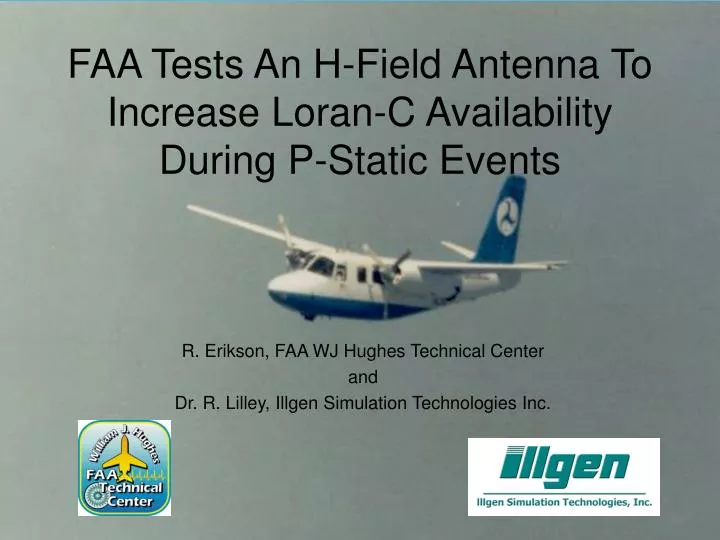
FAA Tests An H-Field Antenna To Increase Loran-C Availability During P-Static Events. R. Erikson, FAA WJ Hughes Technical Center and Dr. R. Lilley, Illgen Simulation Technologies Inc. . Background.

E N D
FAA Tests An H-Field Antenna To Increase Loran-C Availability During P-Static Events R. Erikson, FAA WJ Hughes Technical Center and Dr. R. Lilley, Illgen Simulation Technologies Inc.
Background • Late 1980’s criticism: Precipitation static (P-static) said to deny Loran-C guidance just when you need it the most -- in instrument meterological conditions. FAA/Illgen 11-6-03
Electrical Noise Generated in Flight • Aircraft Charging • Electrons knocked free from particles of ice or water (triboelectric process) • MIL-STD-464 - charge based on • Wetted frontal area • Cloud & precipitation type • Aircraft speed • Aircraft Discharging or Equalization • Arcs • Different elements of airframe are charged to different voltages • Broadband noise, energetic FAA/Illgen 11-6-03
Electrical Noise Generated in Flight - cont. • Aircraft Discharging or Equalization • Streamers • Low-current arcs form across dielectric surfaces ( windscreens, radomes) • Corona • Packets of charge leaving the trailing edge • Constant amplitude, rate variable • Low current FAA/Illgen 11-6-03
Solutions • Add static dischargers • Good aircraft maintenance • Magnetic-loop (“h-field”) antenna FAA/Illgen 11-6-03
Why Do We Expect H-field Antennas Will Increase Availability? • Studies at Ohio University • Aircraft: DC-3, Piper Saratoga, Bonanza • Methods: • Ground electrostatic calibration • Flight • Equipment: • Loran with e- and h-field antennas • Wideband recordings • Omega history and experience FAA/Illgen 11-6-03
E-Field 5 - 1 H-Field E-Field SNR (dB) - 5 Severe P-Static (Snow) - 9 Secondary Y NorthEast U.S. (9960) Time 0 = 0734 EST on 20 March 2000 Flight from N39 W82 to N36 W83 Avionics Engineering CenterOhio University, Athens, OH 45701 Aircraft: Beechcraft V35A Loran Receivers: II Morrow Apollo 612A (TSO’d) E-field: II Morrow A-16 Whip (TSO’d) H-field: King Radio ADF (TSO’d) 0 20 40 60 80 100 120 Time in minutes E-Field - H-Field Comparison FAA/Illgen 11-6-03
SNR Time Difference Vbaseline Vmax Vbaseline Vmax Vbaseline - no charge on airplane Vmax - maximum charging, 27 KV and 51 uA Time Difference from Seneca, N.Y. station tracked from Athens, Ohio Illgen/Ohio University Results Test performed by Illgen Simulation Technologies, Inc. with support of the Avionics Engineering Center, Ohio University. November 1998, using equipment provided by Locus (e-field) and Megapulse (h-field). FAA/Illgen 11-6-03
Test performed by Illgen Simulation Technologies, Inc. with support of the Avionics Engineering Center, Ohio University. November 1998, using equipment provided by Locus (e-field) and Megapulse (h-field). FAA/Illgen 11-6-03
You want to do what? • Charge aircraft with 50,000 volt power supply • Install polycarbonate tail boom (stinger) • with a cluster of airframe dischargers, operated "in reverse" FAA/Illgen 11-6-03
FAA Test Program - Overview • Ground based artificial electrostatic charging • Controlled charge rate and quantity • Calibrate field mill and discharge currents • Measure Loran-C SNR performance • Flight test naturally occurring charging • Measure aircraft potential, discharge currents, and Loran-C SNR performance with e- and h-field antennas • Flight test with artificial charging • Measure aircraft potential, discharge currents, and Loran-C SNR performance FAA/Illgen 11-6-03
Equipment Suite • SatMate 1020 (h-field and e-field antennas) • Apollo Multi Chain Loran Sensor (MCLS -2010) • Mission Instruments EF-1001 Field Mill • High Voltage Power Supply (50kVa) • Time Space Position Information (TSPI) FAA/Illgen 11-6-03
Work To Date • Safety Plan (work in progress) • Skin map of aircraft to determine loop antenna location • Antennas, field mill, and equipment installed • Hangar tests (on-air signals, simulator) • Preliminary flight check-out FAA/Illgen 11-6-03
Ground Based Artificial Charging Current Metering Panel: uA Meter Array ------------ Rudder Rt Tail Lt Tail Lt Wing Rt Wing Rt Pad Lt Pad Nose Pad ---------- Total Current Tail tip discharge monitor Ion collection fixtures 3 Ion flood fixtures with corona ball and ignition lead Variable HV Power Supply Acrylic pads with leakage guard bands to isolate tires FAA/Illgen 11-6-03
Illgen/ Ohio University Tests FAA/Illgen 11-6-03
FAA N-50 FAA/Illgen 11-6-03
Check-out N-50 Flight 10-22-03 Checkout of field mill data collection (Raw data. Rogue zeros are now gone!) FAA/Illgen 11-6-03
FAA N-50 Flight 10-22-03Check out receivers data collection and observe airframe potential in cloud. Apollo: Outputs an SNR "number". A number in the 90s likely represents SNR of about +8 dB. (To be calibrated.) Blue=SatMate e-field, Red=SatMate h-field, Black=Apollo e-field, legacy (hard-limited) FAA/Illgen 11-6-03