Download
1 / 29
300 likes | 675 Views
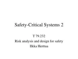
Safety-Critical Systems 2 Requirement Engineering. T- 79.5303 Spring 2006 Ilkka Herttua. Safety Context Diagram. HUMAN. PROCESS. - Operating Rules. SYSTEM. - Hardware - Software. Critical Applications. Computer based systems used in avionics, chemical process and nuclear power plants.

E N D
Safety-Critical Systems 2Requirement Engineering T- 79.5303 Spring 2006 Ilkka Herttua
Safety Context Diagram HUMAN PROCESS - Operating Rules SYSTEM - Hardware - Software
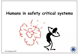
Critical Applications • Computer based systems used in avionics, chemical process and nuclear power plants. • A failure in the system endangers human lives directly or through environment pollution. Large scale economic influence.
Safety Definition • Safety: Safety is a property of a system that it will not endanger human life or the environment. • Safety-Critical System: A system that is intended to achieve, on its own, the necessary level of safety integrity for the implementation of the required safety functions.
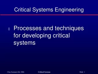
Developing safety-related systems • To achieve safety: - safety requirements (avoiding hazards, risks) - quality management (follow up process) - design / system architecture (reliability) - defined design/manufacture processes - certification and approval processes - known behaviour of the system in all conditions
Risk Analysis • Risk is a combination of the severity (class) and frequency (probability) of the hazardous event. • Risk Analysis is a process of evaluating the probability of hazardous events. • The Value of life?? Value of life is estimated between 0.75M –2M GBP. USA numbers higher.
Risk Analysis • Classes: - Catastrophic – multiple deaths >10 - Critical – a death or severe injuries - Marginal – a severe injury - Insignificant – a minor injury • Frequency Categories: Frequent 0,1 events/year Probable 0,01 Occasional 0,001 Remote 0,0001 Improbable 0,00001 Incredible 0,000001
Hazard Analysis • A Hazard is situation in which there is actual or potential danger to people or to environment. • Analytical techniques: - Failure modes and effects analysis (FMEA) - Failure modes, effects and criticality analysis (FMECA) - Hazard and operability studies (HAZOP) - Event tree analysis (ETA) - Fault tree analysis (FTA)
Fault Tree Analysis 1 The diagram shows a heater controller for a tank of toxic liquid. The computer controls the heater using a power switch on the basis of information obtained from a temperature sensor. The sensor is connected to the computer via an electronic interface that supplies a binary signal indicating when the liquid is up to its required temperature. The top event of the fault tree is the liquid being heated above its required temperature.
Fault event not fully traced to its source Basic event, input Fault event resulting from other events OR connection
Risk acceptability • National/international decision – level of an acceptable loss (ethical, political and economical) Risk Analysis Evaluation: ALARP – as low as reasonable practical (UK, USA) “Societal risk has to be examined when there is a possibility of a catastrophe involving a large number of casualties” GAMAB – Globalement Au Moins Aussi Bon = not greater than before (France) “All new systems must offer a level of risk globally at least as good as the one offered by any equivalent existing system” MEM – minimum endogenous mortality “Hazard due to a new system would not significantly augment the figure of the minimum endogenous mortality for an individual”
Risk acceptability Tolerable hazard rate (THR) – A hazard rate which guarantees that the resulting risk does not exceed a target individual risk SIL 4 = 10-9 < THR < 10-8 per hour and per function SIL 3 = 10-8 < THR < 10-7 SIL 2 = 10-7 < THR < 10-6 SIL 1 = 10-6 < THR < 10-5 Potential Loss of Life (PLL) expected number of casualties per year SIL = safety integrity level
Current situation / critical systems • Based on the data on recent failures of critical systems, the following can be concluded: • Failures become more and more distributed and often nation-wide (e.g. air traffic control and commercial systems like credit card denial of authorisation) • The source of failure is more rarely in hardware (physical faults), and more frequently in system design or end-user operation / interaction (software). • The harm caused by failures is mostly economical, but sometimes health and safety concerns are also involved. • Failures can impact many different aspects of dependability (dependability = ability to deliver service that can justifiably be trusted).
Requirements Model Requirements Analysis Test Scenarios Test Scenarios System Acceptance Requirements Document Functional / Architechural - Model System Integration & Test Systems Analysis & Design Specification Document Knowledge Base * Software Design Module Integration & Test Software Implementation & Unit Test * Configuration controlled Knowledge that is increasing in Understanding until Completion of the System: • Requirements Documentation • Requirements Traceability • Model Data/Parameters • Test Definition/Vectors V - Lifecycle model
Safety Requirements • Requirements are stakeholders (customer) demands – what they want the system to do. Not defining how !!! => specification • Safety requirements are defining what the system must do and must not do in order to ensure safety. Both positive and negative functionality.
Specification • Supplier instructions how to build the system. Derived from the required functionality = Requirements. Requirements R + Domain Knowledge D => Specification S
Where do we go wrong? • Many system failures are not failures to understand R requirements ; they are mistakes inD domain knowledge • A NYC subway train crashed into the rear end of another train on 5th June 1995. The motorman ran through a red light. The safety system did apply the emergency brakes. However the ...signal spacing was set in 1918, when trains were shorter, lighter and slower, and the emergency brake system could not stop the train in time. • Are you sure?
Requirement Engineering Right Requirements • Ways to refine Requirements - complete – linking to hazards (possible dangerous events) - correct – testing & modelling - consistent – semi/formal language - unambiguous – text in real English
Requirement Engineering Tools – Doors (Telelogic) • Data base and configuration management • History, traceability and linking
Requirements Management with DOORS Slides provided by Telelogic/ Quality Systems & Software
Dynamic Object Oriented Requirements System Interfaces Configuration- management Requirements Links DOORS Effizienz Reports Analysis Multiuser-Databank User Accounts Change Proposal System Filter, Views Text Processing Templates, Standards Capture, Link, Trace, Analyse, Administer
Consists of numerous Modules • One Document, • Group of related Information • Requirements, Tests, Specifications, • Change Requests, etc Object Object Links Object Dataof a Module Object Attribute Attribute • Characteristics of Objectsor Links • Dateof last Change, Priority, Status, Costs, ... Attribute Relation between two Objects Terminology in DOORS Project Module
Traceability in DOORS Architectural Design Requirement Specification Test Plan Follow Customer Ammendments through all the Documentation
Traceability - Requirements from Scenarios Boat lifted Boat loaded Two people shall be able to lift the boat onto the roof of the average saloon car. Boat on car Ready to sail Boat unloaded Mast rigged Center-plate rigged traceability Boat rigged To have sailed and survived Rudder rigged The sailor shall be able to perform a tacking manoeuvre. Goal hierarchy Gibed user requirements Tacked Boat manoeuvred Sailed Cruised The sailor shall be able to contact the coastguard when the boat is capsized. Boat righted Boat capsized Returned home Coast guard contacted Gone ashore
Requirements Model Requirements Analysis Test Scenarios Test Scenarios System Acceptance Requirements Document Functional / Architechural - Model System Integration & Test Systems Analysis & Design Specification Document Knowledge Base * Software Design Module Integration & Test Software Implementation & Unit Test * Configuration controlled Knowledge that is increasing in Understanding until Completion of the System: • Requirements Documentation • Requirements Traceability • Model Data/Parameters • Test Definition/Vectors V - Lifecycle model
Additional home assignments • From Neil Storey’s book Safety Critical Computer Systems • 1.12 (Please define primary, functional and indirect safety) • 2.4 (Please define unavailability) Email by 1 March to herttua@eurolock.org