Download
1 / 15
440 likes | 1.24k Views
Radiation Detection. ionization chambers (dosimeters, pulse chambers, particle track chambers). scintillation detectors. semiconductor detectors. photographic emulsions. interaction with atoms. 2. 1. 1. EXCITATION.

E N D
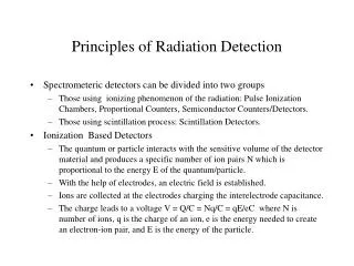
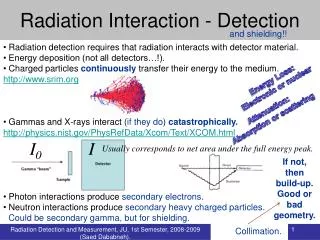
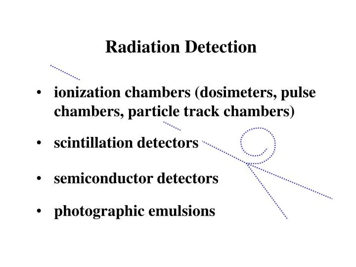
Radiation Detection • ionization chambers (dosimeters, pulse chambers, particle track chambers) • scintillation detectors • semiconductor detectors • photographic emulsions
interaction with atoms 2 1 1. EXCITATION (Energy of the radiation used for increasing the internal energy of the atom) 2. IONIZATION (Radiation separates the atom into an electron and an ion.) E = h
ionization level Particles of different radiation carry different amounts of energy. typical ionization energy range: 10 - 25 eV number of primary ions: -radiation - 100 -, -radiation - 100 000
+ - + - recombination Ions may collide inelastically to form a neutral atom. + The probability of recombination: - n - number of pairs of ions - recombination coefficient Excess energy is released in the form of electromagnetic radiation.
+ + + + V + + + + V electrometer ionization chamber dose meters pocket ion chamber electroscope condenser-R-meter
+ + + - - - + + + - - - + + + - - - charge collection • With no field the ions eventually recombine leaving no record of radiation. • With a weak field some ions recombine and some are discharged by the electrodes. • With a sufficiently strong (but limited) field all the ions are discharged by the electrodes (saturation). • Further increase of the field results in an avalanche discharge.
gas-amplification factor The collected charge is proportional to the charge of the primary ions. The proportionality coefficient is called the gas-amplification factor. recombination region: ions remain in the chamber for an extended time; some ions recombine and are not collected (factor < 1) saturation region: no time for recombination; no energy for secondary ionization (factor = 1) (factor > 1) avalanche ionization: ions achieve sufficient energy to ionize neutron atoms
+ a b Geiger – Müller (G-M) tube concentric electric field: ionization potential: required field: a ~ 0.08 mm where is the mean free path of the ions. The strongest field is at the anode.
1010 F E 108 C pulse size 106 D 104 B 102 A 1 0 500 250 750 tube voltage G-M tube operation regimes A – recombination region B – saturation region (dependent on energy) C – proportional region D – limited proportionality E – Geiger region (independent of energy) F – continuous discharge
electric pulse in the Geiger region space charge Q From Gauss’s law q E2 E1 , r0 With a relatively small signal V const and the charge on the central wire is Typically the space charge reaches the cathode and gets neutralized in 100 s.
quenching the discharge Neutralization of ion results in photoelectric effect. The electrons liberated from the cathode often trigger self-perpetuating series of discharge at a frequency determined by the circuit time constant. Quenching circuits or quenching gases are used to prevent secondary discharge. Properties of a quenching gas: • ionization energy lower than that of the main gas and the work function of the cathode material • absorb UV • dissociate rather than radiate UV
1.0 pulse voltage 0.5 1.0 8 0 2 6 4 time (10-4 s) pulse shape The discharge (slightly) lowers the anode potential. 0.89 V After the discharge the potential of the anode is restored by the high voltage power supply.
amplifier/ discriminator counting circuit HV - + G-M counter The proportional region: gas amplification factor ~ 103 moderately strong pulses; dispersive pulse size; G-M region: gas amplification factor ~ 106 - 107 very sensitive to radiation;
1.0 pulse voltage 0.5 1.0 8 0 2 6 4 time (10-4 s) resolving time The dead time and the recovery time depend on the threshold voltage of the circuit. 0.89 V 0.2 V
300 200 counts per minute 100 0 600 1000 800 1200 tube voltage counting rate A – threshold voltage B – fraction of primary events counted D C E C-D – all primary events counted (plateau) B E – continuous discharge A (a single event results in repetitive spontaneous discharge)