Download
1 / 42
520 likes | 988 Views
Heat Exchanger. Heat exchangers can be described as: they include all devices that are designed for exchanging heat. Only heat exchangers that are meant to exchange heat between two fluids are taken into account.

E N D
Heat Exchanger Heat exchangers can be described as: they include all devices that aredesigned for exchanging heat. Only heat exchangers that are meant to exchange heat between two fluids are taken intoaccount. These fluids can be gasses as well as liquids.It is still difficult to have an overview, and a classification needs to be made. It is possible toclassify heat exchangers in a number of ways.
Classification Heat Exchangers 1.Classification of heat exchangers depending on the basic of the fluid paths through the heatexchanger. Difference is made between : • parallel flow, • counter flow • and cross flow.
Classification This is a heat exchangers that is found on the top buildings and is for instance needed for air conditioning inside. Here a fluid is leaded between the plates at the top of the heat exchanger and flows horizontally. Air is blown vertically against the plates to cool the fluid inside. cross flow air to liquid heat exchanger
Classification The second classification made, is depending on the state of the media in the heat exchanger. Liquid-to-liquid exchangers are those in which two liquids interact. Also gas-to-gas heatexchangers like air preheaters in steam plants and helium-cooled reactor gas turbine plantshave to be mentioned. These devices operate with heat transfer coefficients that are betweenten and one hundred times lower than the coefficients of liquid-to-liquid exchangers. Gastogasexchangers are general much larger and heavier if a same amount of transferred heat isdemanded. The third type is the liquid-to-gas heat exchanger (or vice versa), usually water and air are used,for instance in automotive radiators. Because of thelower heat transfer coefficients on the gas-side there are usually fines placed on the exchangingsurfaces.
Classification The third classification method is based the purpose of heat exchanger. The last classification is actually the most important choice of the designer of a heatexchanging system. This is the choice what kind of construction he is going to use.
Shell-and-tube-heat exchanger with one shell pass and one tube pass; cross- counterflow operation
Regenerative Heat Exchangers The regenerator represents class of heat exchangers in which heat is alternately stored and removed from a surface This heat transfer surface is usually referred to as the matrix of the regenerator. For continuous operation, the matrix must be moved into and out of the fixed hot and cold fluid streams. In this case, the regenerator is called a rotary regenerator. If, on the other hand, the hot and cold fluid streams are switched into and out of the matrix, the the regenerator is referred to as a fixed matrix regenerator.
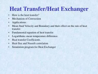
Heat Transfer of Heat Exchanger • How is the heat transfer? • Mechanism of Convection • Applications . • Mean fluid Velocity and Boundary and their effect on the rate of heat transfer. • Fundamental equation of heat transfer • Logarithmic-mean temperature difference. • Heat transfer Coefficients. • Heat flux and Nusselt correlation • Simulation program for Heat Exchanger
How is the heat transfer? • Heat can transfer between the surface of a solid conductor and the surrounding medium whenever temperature gradient exists. Conduction Convection Natural convection Forced Convection
Natural and forced Convection • Natural convection occurs whenever heat flows between a solid and fluid, or between fluid layers. • As a result of heat exchange Change in density of effective fluid layers taken place, which causes upward flow of heated fluid. If this motion is associated with heat transfer mechanism only, then it is called Natural Convection
Forced Convection • If this motion is associated by mechanical means such as pumps, gravity or fans, the movement of the fluid is enforced. • And in this case, we then speak of Forced convection.
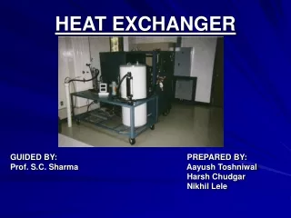
Heat Exchangers • A device whose primary purpose is the transfer of energy between two fluids is named a Heat Exchanger.
Applications of Heat Exchangers Heat Exchangers prevent car engine overheating and increase efficiency Heat exchangers are used in Industry for heat transfer Heat exchangers are used in AC and furnaces
The closed-type exchanger is the most popular one. • One example of this type is the Double pipe exchanger. • In this type, the hot and cold fluid streams do not come into direct contact with each other. They are separated by a tube wall or flat plate.
0 0 0 0 • Control Volume COLD Qh HOT Cross Section Area Thermal Boundary Layer Principle of Heat Exchanger • First Law of Thermodynamic: “Energy is conserved.”
THERMAL BOUNDARY LAYER Q hot Q cold Region III: Solid – Cold Liquid Convection NEWTON’S LAW OF CCOLING Energy moves from hot fluid to a surface by convection, through the wall by conduction, and then by convection from the surface to the cold fluid. Th Ti,wall To,wall Tc Region I : Hot Liquid-Solid Convection NEWTON’S LAW OF CCOLING Region II : Conduction Across Copper Wall FOURIER’S LAW
Velocity distribution and boundary layer When fluid flow through a circular tube of uniform cross-suction and fully developed, The velocity distribution depend on the type of the flow. In laminar flow the volumetric flowrate is a function of the radius. V = volumetric flowrate u = average mean velocity
In turbulent flow, there is no such distribution. • The molecule of the flowing fluid which adjacent to the surface have zero velocity because of mass-attractive forces. Other fluid particles in the vicinity of this layer, when attempting to slid over it, are slow down by viscous forces. Boundary layer r
h Tube wall heating • Accordingly the temperature gradient is larger at the wall and through the viscous sub-layer, and small in the turbulent core. • The reason for this is 1) Heat must transfer through the boundary layer by conduction. 2) Most of the fluid have a low thermal conductivity (k) 3) While in the turbulent core there are a rapid moving eddies, which they are equalizing the temperature. cooling
+ ri ro U = The Overall Heat Transfer Coefficient [W/m.K] Region I : Hot Liquid – Solid Convection Region II : Conduction Across Copper Wall Region III : Solid – Cold Liquid Convection
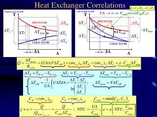
Calculating U using Log Mean Temperature Hot Stream : Cold Stream: Log Mean Temperature
T 10 T 2 T 1 T 4 T 5 T 6 T 3 T 9 T 8 1 2 T 7 P ara ll e l Fl ow T 10 1 2 T 2 T 1 T 4 T 5 T3 T4 T6 T 3 T 6 T6 ∆ T 1 T1 Wall ∆ T T 9 2 T 8 T 7 T2 T7 T8 Co un t e r - C u r re n t F l ow T9 T10 ∆ A A A Log Mean Temperature evaluation COUNTER CURRENT FLOW CON CURRENT FLOW
1 2 T3 T4 T6 T6 T1 Wall T2 T7 T8 T9 T10 A
h DIMENSIONLESS ANALYSIS TO CHARACTERIZE A HEAT EXCHANGER • Further Simplification: Can Be Obtained from 2 set of experiments One set, run for constant Pr And second set, run for constant Re
Empirical Correlation • For laminar flow • Nu = 1.62 (Re*Pr*L/D) • For turbulent flow • Good To Predict within 20% • Conditions: L/D > 10 • 0.6 < Pr < 16,700 • Re > 20,000
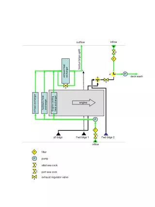
Experimental Switch for concurrent and countercurrent flow • Temperature • Indicator Hot Flow Rotameters Cold Flow rotameter Apparatus Heat Controller Temperature Controller • Two copper concentric pipes • Inner pipe (ID = 7.9 mm, OD = 9.5 mm, L = 1.05 m) • Outer pipe (ID = 11.1 mm, OD = 12.7 mm) • Thermocouples placed at 10 locations along exchanger, T1 through T10
Theoretical trend y = 0.8002x – 3.0841 Examples of Exp. Results Theoretical trend y = 0.026x Experimental trend y = 0.0175x – 4.049 Experimental trend y = 0.7966x – 3.5415 Theoretical trend y = 0.3317x + 4.2533 Experimental Nu = 0.0175Re0.7966Pr0.4622 Theoretical Nu = 0.026Re0.8Pr0.33 Experimental trend y = 0.4622x – 3.8097
Effect of core tube velocity on the local and over all Heat Transfer coefficients