Download

1 / 71
740 likes | 1.03k Views
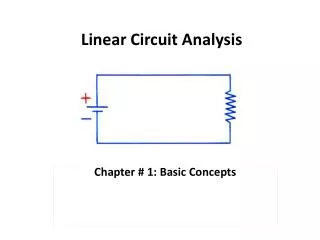
Linear Circuit Analysis. In an oscilloscope a timing signal called a horizontal sweep acts as a time base, which allows one to view measured input signals as a function of time.

E N D
In an oscilloscope a timing signal called a horizontal sweep acts as a time base, which allows one to view measured input signals as a function of time.
In practice, the linear increase in voltage is approximated by the “linear” part of an exponential response of an RC circuit.
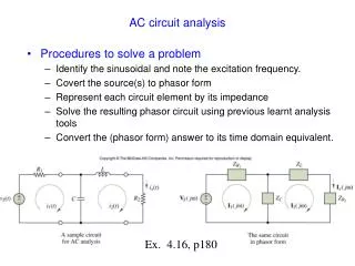
R + C US _ R + L US _ First-Order RL and RC Circuits 1. What is a first-order circuit? A first-order circuit is characterized by a first-order differential equation. It consists of resistors and the equivalent of one energy storage element. Typical examples of first-order circuits: (a) First-Order RL circuit (b) First-Order RC circuit
R + C US _ + _ Interconnections of sources, resistors, capacitors, and inductors lead to new and fascinating circuit behavior. A loop equation leads to since First-Order RC circuit or , equivalently, This equation is called Constant-coefficient first-order linear differential equation Apply duality principle,
2. Some mathematical preliminaries RC circuit first-order differential equation RL circuit first-order differential equation The first-order RL and RC circuits have differential equation models of the form or , equivalently, valid for t≥t0, where x(t0)=x0 is the initial condition. The term f(t) denotes a forcing function. Usually, f(t) is a linear function of the input excitations to the circuit. The parameter λdenotes a natural frequency of the circuit.
or The main purpose of this chapter is to find a solution to the differential equation. The solution to the equation for t≥t0 has the form (1) Satisfies the differential equation (2) Satisfies the correct initial condition, x(t0)=x0
Integrating factor method First step, multiply both sides of the equation by a so-called integrating factor e-λt. By the product rule for differentiation, Integrate both sides of the equation from t0 to t as follows
+ + C R _ _ + L R _ 3. Source-free or zero-input response A parallel connection of a resistor with an inductor or capacitor without a source. In these circuits, one assumes the presence of an initial inductor current or initial capacitor voltage. (a) KCL implies (b) KVL implies Both differential equation models have the same general form,
The solution to the equation for t≥t0 has the form Where τ is a special constant called the time constant of the circuit. The response for t≥t0 of the undriven RL and RC circuit are, respectively, given by RL circuit RC circuit The time constant of the circuit is the time it takes for the source-free circuit response to drop to e-1=0.368 of its initial value.
Linear Resistive circuit No independent sources C C L Linear Resistive circuit No independent sources + _ + L _ For more general circuits, those containing multiple resistors and dependent sources, it is necessary to use the Thevenin equivalent resistance seen by the inductor or capacitor in place of the R. Thevenin equivalent Thevenin equivalent
+ _ Example 1. For the circuit of the figure, find iL(t) and uL(t) for t ≥0 given that iL(0-)=10A and the switch S closes at t=0.4s. Then compute the energy dissipated in the 5Ω resistor over the time interval [0.4, ∞).
R + + + + u(t) R u(t) C US US _ _ K _ _ K 一阶电路的初始条件 稳态(steady state) 代数方程描述 瞬态(transient state) 微分方程描述 (1)问题的提出 US 过渡期为零 换路 过渡状态 过渡状态 US 换路 第一个稳定状态 第二个稳定状态 第三个稳定状态
C + _ 当 为有限值 (2)电路的初始条件 ① t=0- 和 t =0+ 的概念 t =0- 换路前一瞬间 认为换路在 t =0 时刻进行 t =0+ 换路后一瞬间 初始条件为t =0+时u、i 及其各阶导数的值 ②电容的初始条件 t=0+时 电荷守恒 换路瞬间,若电容电流保持为有限值,则电容电压(电荷)换路前后保持不变。
+ _ L 当 为有限值 ③电感的初始条件 t=0+时 磁链守恒 换路瞬间,若电感电压保持为有限值,则电感电流(磁链)换路前后保持不变。 ④换路定律 反映了能量不能跃变 换路瞬间,若电容电流保持为有限值, 则电容电压(电荷)换路前后保持不变。 换路瞬间,若电感电压保持为有限值, 则电感电流(磁链)换路前后保持不变。
电路如图所示,试求 。 ① 画出 电路,求出 ③ 画出 电路,求出 + + + + _ _ _ _ 电路 电路 + + _ _ 例1 解: 电容开路 电容用电压源替代 ② 由换路定律 可见,
电路如图所示,试求 。 ③ 画出 电路,求出 ① 画出 电路,求出 + + _ _ + + + + _ _ 电路 电路 _ _ 例2 解: 电感短路 电感用电流源替代 ② 由换路定律 可见,
求解初始条件的步骤 ① 画 0- 等效电路,即换路前电路(稳定状态),求 uC(0-) 和iL(0-)。 电容相当于开路 其中 电感相当于短路 ② 由换路定律得 uC(0+) 和 iL(0+)。 ③ 画 0+ 等效电路,即换路后的电路。 电容用电压源来替代,大小为 uC(0+) 其中 电感用电流源来替代,大小为 iL(0+)。 电压源和电流源的方向均与原来的电压、电流方向一致。 ④ 由 0+ 电路求所需各变量的 0+ 值。
电路如图所示,试求 , 。 ① 画出 电路,求出 , + _ _ _ 电路 电路 + + + + _ _ ③ 画出 电路,求出 , 例3 解: ② 由换路定律
+ + + _ + + + _ _ + _ _ _ _ 电路 电路 + _ 例4 电路如图所示,试求开关K闭合瞬间各支路的电流和电感上的电压。 解:
_ + _ + + 电路 电路 _ + _ + _ + + _ _ 例5 电路如图所示,试求开关K闭合瞬间流过它的电流值。 解:
单位阶跃函数及分段常量信号 单位阶跃函数 延时(delayed)单位阶跃函数 分段常量信号(piecewise-constant signal) (矩形)脉冲(pulse) 脉冲串(pulse train)
运用阶跃函数和延时阶跃函数,分段常量信号可以表示为一系列阶跃信号之和。运用阶跃函数和延时阶跃函数,分段常量信号可以表示为一系列阶跃信号之和。
Example 8.2. For the circuit of the figure, find iL(t) and uL(t) for t ≥0 given that iL(0-)=10A and the switch S closes at t=0.4s. Then compute the energy dissipated in the 5Ω resistor over the time interval [0.4, ∞). + _ Solution Step 1. With switch S open, compute the response for 0≤t ≤0.4s. From the continuity property of the inductor current, Step 2. With switch S closed, compute the response for t≥0.4s.
Step 3. Write the complete response as a single expression. Step 4. Plot the complete response. The 0.4s time constant has a much faster rate of decay than the lengthy 2s time constant.
+ _ Step 5. Compute uL(t). for 0≤t ≤0.4s, in particular, hence, for t ≥0.4s, in particular, Step 6. Compute energy dissipated in the 5Ω resistor over the time interval [0.4, ∞).
+ _ Example 8.3. Find uC(t) for t ≥0 for the circuit of the figure given that uC(0)=9V. Solution Step 1. Compute the response for 0≤t ≤1s. By the continuity of the capacitor voltage, hence, Step 2. Compute the response for t ≥ 1s. Step 3. Use step functions to specify the complete response.
Step 4. Obtain a plot of the response. Here the part of the response with the 0.3s time constant shows a greater rate of decay than the longer 0.8s time constant.
+ _ Exercise. Suppose that in example 2 the switch moves to the 4.5Ω resistor at t=0.5s instead of 1s. Compute the value uC(t) at t=1.2s.
+ + + _ _ _ Example 8.4. Find uC(t) for the circuit of the figure, assuming that gm=0.75S and uC(0-)=10V. Solution It is straightforward to show that the Thevenin equivalent seen by the capacitor is a negative resistance, Thevenin equivalent hence,
Because of the negative resistance, this response grows exponentially, as shown in the figure. A circuit having a response that increases without bound is said to be unstable. Negative resistance causes capacitor voltage to increase without bound.
+ + _ _ Exercise. In example 3, let gm=0.125S. Find the equivalent resistance seen by the capacitor and uC(t), t ≥0.
+ + _ _ 示例 已知图示电路中的电容原本充有 24V 电压,求K闭合后,电容电压和各支路电流随时间变化的规律。 解: 本题为求解一阶 RC 电路零输入响应问题 则有 又由已知条件 等效电路 t > 0 利用并联分流,得
+ + _ + _ _ 示例 t = 0 时 ,开关K由1→2,求电感电压和电流。 RL电路零输入响应问题 解:
小结 ① 一阶电路的零输入响应是由储能元件的初值引起的响应, 都是由初始值衰减为零的指数衰减函数。 RC 电路 RL 电路 ② 衰减快慢取决于时间常数 。 RC 电路 RL 电路 R为与动态元件相连的一端口电路的等效电阻。 ③ 同一电路中所有响应具有相同的时间常数。 ④ 一阶电路的零输入响应和初始值成正比,称为零输入线性。
Linear Resistive circuit With independent sources C L Linear Resistive circuit With independent sources + + + L _ _ _ + + C _ _ 4. DC or step response of first-order circuits This section takes up the calculation of voltage and current responses when constant voltage or constant current sources are present. Thevenin equivalent Thevenin equivalent
+ + L _ _ + + C _ _ Deriving the differential equation models characterizing each circuit’s voltage and current responses. By KVL and Ohm’ law, By KCL and Ohm’ law,
C + + L _ _ Exercise. Constant differential equation models for the parallel RL and RC circuits of the figure. Note that these circuits are Norton equivalents of those in the figure. Again choose iL(t) as the response for the RL circuit and uC(t) as the response for the RC circuit. Answers:
Observe that four differential equations have the same structure: for RL case where for RC case And the general formula for solving such a differential equation:
where as long as x(t) is a capacitor voltage or inductor current, and f(τ)=F is a constant (nonimpulsive) forcing function. Which is valid for t≥t0. After some interpretation, this formula will serve as a basis for computing the response to RL and RC circuits driven by constant sources.
then if for RL case for RC case Hence, the solution of the differential equation given constant or dc excitation becomes for RL case for RC case
+ + _ _ Example 8.5. For the circuit of the figure, suppose a 10V unit step excitation is applied at t=1 when it is found that the inductor current is iL(1-)=1A. The 10V excitation is represented mathematically as uin(t)=10u(t-1)V for t≥1. Find iL(t) and uL(t) for t≥1. Solution Step 1. Determine the circuit’s differential equation model. where the time constant Step 2. Determine the form of the response.
+ + _ _ Step 3. Compute iL(∞) and set forth the final expression for iL(t). replace the inductor by a short circuit, and since It follows that, Step 4. Plot iL(t).
Exercise. Verify that in example 4, uL(t) can be obtained without differentiation by + + Specifically, we need only compute , , and the time constant or . _ _ Step 5. Compute uL(t). Exercise. In example 4, suppose R is changed to 4Ω. Find iL(t) at t=2s.
+ + _ _ Example 8.6. The source in the circuit of the figure furnishes a 12V excitation for t<0 and a 24V excitation for t≥0, denoted by uin(t)=12u(-t)+24u(t)V. The switch in the circuit closes at t=10s. First determine the value of the capacitor voltage at t=0-, which by continuity equals uC(0+). Next determine uC(t) for all t≥0. Solution Step 1. Compute initial capacitor voltage Step 2. Obtain uC(t) for 0≤t ≤ 10s.
+ + + + _ _ _ _ Step 3. Compute the initial condition for the interval t>10. Step 4. Find uC(t) for t>10. Thevenin equivalent Step 5. Set forth the complete response using step functions.
Step 6. Plot uC(t). Exercise. Suppose the switch in example 5 opens again at t=20s. Find uC(t) at t=25s.
+ + _ _ 示例 t = 0 时 , 开关K闭合,已知 uC(0-) = 0V,求(1)电容电压和电流;(2)uC=80V 时的充电时间 t。 (1) RC 电路零状态响应问题 解: (2)设经过 t秒,uC=80V
+ + _ _ 例1 t = 0 时 , 开关K打开,求 t > 0 后 iL,uL 的变化规律 。 解: RL 电路零状态响应问题,先化简电路
+ + + + _ _ _ _ 例2 t = 0 时 , 开关K打开,求 t > 0 后 iL,uL以及电流源两端的电压 u。 解: RL 电路零状态响应问题,先化简电路