Download
1 / 20
200 likes | 337 Views
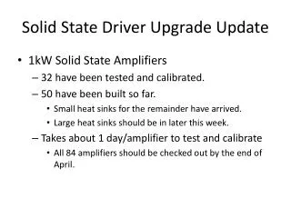
Upgrade Capabilities of the JLab FEL Driver. Chris Tennant Jefferson Laboratory March 15, 2013. “Workshop to Explore Physics Opportunities with Intense, Polarized Electron Beams up to 300 MeV ” . Review of the Jefferson Lab FEL Driver Upgrade scenarios

E N D
Upgrade Capabilities of the JLab FEL Driver Chris Tennant Jefferson Laboratory March 15, 2013 “Workshop to Explore Physics Opportunities with Intense, Polarized Electron Beams up to 300 MeV”
Review of the Jefferson Lab FEL Driver Upgrade scenarios Flexible machine, many options available Present capabilities DarkLight experiment Preliminary S2E for low charge understanding low-charge operation Experimental hall transport line Fixed-target experimental program Capabilities of RF drive Incorporating a polarized injector Maintain high-charge gun capabilities Key Components Summary Outline
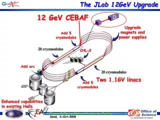
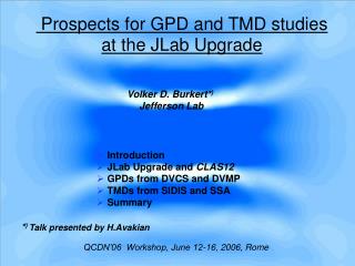
Jefferson Lab FEL Driver: 2 ERLs DC Gun • 350 keV DC photocathode gun, 9 MeV booster, Penner bend merge • 3-cryomodule linac • Bates-bend arcs • longitudinal matching/bunch compression in • chicane for IR • arc/bypass for UV (“chicaneless”) • energy compression during recovery • nonlinear compaction management IR Wiggler SRF Linac Bunching Chicane THz Line UV FEL Transport Line Dump IR FEL: 14+ kW at 1.6 microns, several kW at multiple wavelengths UV FEL: High power (100+ W) at 70 and 400 nm, coherent harmonics into VUV (10 eV) THz Beamline: 10s of W at (0.2-1.5) THz
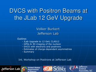
Upgrade Scenarios 130 180 300 360 260 600 750 75 300 120 No Yes Experimental Hall DL Upgrade Polarized e- Injector RF Drive (300 kW) Transport Line 100 MV Cryomodule Two 100 MV Cryomodules
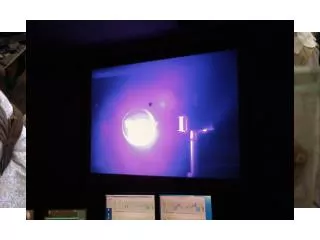
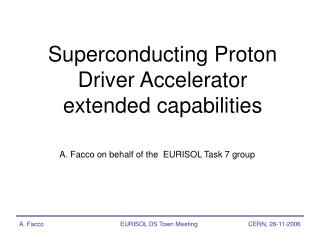
DarkLight Experiment • 450 kW (4.5 mA CW at 100 MeV) through 2 mm aperture for 8 hours • Clean transmission, low beam loss (6 ppm) • Achieved small beam size (50 μmrms) • (Note: performed at 60 pC/bunch) 1 mm 1 mm sx = 50 mm sy = 52 mm (courtesy P. Evtushenko)
DarkLight with 20 pC • 20 pC injector solution, optimized for beam brightness (courtesy Fay Hannon) • Transverse emittance preserved (< 1 mm-mrad)
DarkLight with 20 pC • Physical phase space at the location of the DarkLight cube sx,y = 11.5 um
Longitudinal Match D C A B D C B 1.9 MeV A B D C 30 ps
Beam Quality Issues at Low Charge • Coherent Synchrotron Radiation • should not be an issue; reduced charge, no bunch compression • Space charge • charge density may be comparable • Halo • Due to flexibility of machine, have some level of control • Low-charge operation • Beam can become very bright, care must be taken with longitudinal phase space which can become “spindly/thready”
Transport Line to Experimental Hall • Avoid interferences with lab infrastructure for new (fixed-target) experimental hall • Need a spectrometer to phase linac for 1-pass operation • Preserve beam quality (courtesy D. Douglas)
Capabilities: 120 kW RF Drive 20 pC at 75 MHz 2 pC at 750 MHz 2.7 pC at 75 MHz 0.27 pC at 750 MHz
Capabilities: 300 kW RF Drive 50 pC at 75 MHz 5 pC at 750 MHz 6.7 pC at 75 MHz 0.67 pC at 750 MHz
Want to retain functionality of current gun – which is optimized for high charge install gun within FEL “ring” and use 180° arc to merge to linac Polarized Electron Injector 350 kV 200 kV (under construction)
4-quad matching section + 4-period FODO arc Polarized Injector: Merger
Push 100K particles through with PARMELA Suffers no significant transverse emittance degradation The arc has M56 = 0.25 m; with initial chirp on bunch from booster, beam gets compressed a good thing Polarized Injector: Merger
Longitudinal Match D C A B B D C 0.4 MeV A B D C 10 ps
Energy Spread at Linac Exit DEfull=1.8x10⁻³ DEfull=1.5x10⁻² Current merger Arc merger (polarized source)
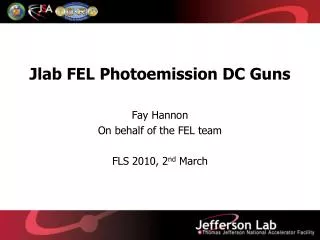
Polarized Gun: new generation gun design (350 kV) DC Power Supply: Drive Laser: Buncher: reuse from FEL injector (soon to be replaced) Booster: reuse from FEL injector (soon to be replaced) Merger Design: FODO arc to allow placement of gun within FEL ring Key Components to Upgrade(s) • Currently, the machine can provide unpolarized beam for internal target experiments (e.g. DarkLight) • To support a fixed-target program with polarized beam requires: Injector Merger
Cryomodules: 100 MV module by end of 2013; increase energy further by adding two more refurbished cryomodules RF Power: installing 12 GeV klystrons would increase our capacity from 120 kW (8 kW klystrons) to 300 kW (12 kW klystrons) Recirculator: though specified for 80-210 MeV operation, with modification to the temperature of the cooling water, the hardware is capable of operating at 300 MeV Experimental Hall: civil construction Transport Line: new dipole magnet design required, vacuum chamber Key Components to Upgrade(s) RF Recirculator End Station
Summary *assumes transport line and experimental hall in place (courtesy D. Douglas)