Download
1 / 24
240 likes | 248 Views
SEQUOIA Overview Garrett Granroth (Instrument Scientist) David Vandergriff (Lead Engineer) ARCS/SEQUOIA IDT meeting March 20, 2005. Outline. Overview Progress Procurement Status Installation Status Specific items T 0 chopper Sample Area Magnetic shielding issues Summary.

E N D
SEQUOIA Overview Garrett Granroth (Instrument Scientist) David Vandergriff (Lead Engineer) ARCS/SEQUOIA IDT meeting March 20, 2005
Outline • Overview • Progress • Procurement Status • Installation Status • Specific items • T0 chopper • Sample Area • Magnetic shielding issues • Summary
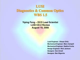
SEQUOIA Overview Beam Stop Core Vessel insert Shutter insert Front End shielding Beamline shielding Get Lost Tube Detectors Fermi Chopper Detector Vessel To Chopper Guide Poured In-Place Shielding Sample Vessel
Instrument Parameters • minimum Dw/Ei < 1.2% • Ei = 10 – 2000 meV • Lengths • Moderator to Fermi chopper 18.0 m • Fermi Chopper to sample 2 m • Sample to Detector 5.5 m • 43m2 of detectors covering 1.2 Sr • Span -30o – -3o, 3o – 60o horizontal, -30o – -3o, 3o – 30o vertical. • ~138,000 pixels
Location SEQUOIA
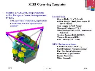
SEQUOIA and ARCS Beam Stop Detector Array Get-Lost Tube Sample Vessel Detector Vessel 5.5 m Fermi Choppers 2 m ARCS Beamstop T0 Chopper 8 m Shutter Insert 10 m CVI
System Overview • Beamline 17/18 “Pit” Area
SEQUOIA Dates • Conceptual Design Review – March 04 • Shutter Insert Guide* on Order with CILAS – April 04 • Critical Decision - 1 (Alternative Selection and Cost Range) approved by DOE (CD-1) – April 04 • Preliminary Design Review – May 04 • Core Vessel Insert* Installed – July 04 • Guide Design Review – August 04 • Post Doc Matthew Stone arrives at HFIR – August 04 • IDT meeting – October 04 • CD-2A and CD-3A (long lead procurements) approved – October 04 • Shutter Inset Guide Installed – December 04 • Engineer Mark Overbay joins the SEQUOIA team to work on Choppers – January 05 • Detector Vessel and Sample Vessel Design Review – February 05 • Shutter installed – February 05 • IPR and CD-3 Review (all procurements) – March 05 • Guide vendor selected – March 05 • Joint ARCS /SEQUOIA IDT meeting – March 05 * Early procurement permitted because these items are time critical
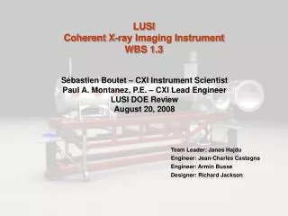
Instrument Procurement Progress Legend: Awarded Vendor chosen Out for bid In next 6 months BOA component Beam Stop Front End shielding Beamline shielding Get Lost Tube Detectors Fermi Chopper Detector Vessel To Chopper Guide Poured in Place shielding SampleVessel
In-Monolith Component Installation • Shutter Insert(Feb 2005) • Core Vessel Insert (Aug 2004) • Shutter Insert guide (Nov 2004)
Core Vessel Insert Installed Aug. 2004 Apr. 2004 Beamline 17
T0 Chopper Vertical axis narrow band width design. • Background reduction • Max Ei = 2 eV • Up to 180 Hz operation. • Constant 31 cm Inconel X-750 to block beam. • Ultimate 160 ksi. • Yield 100 ksi. • Eliminates need for bandwidth chopper. • Working closely with ARCS team • Simplifies shielding design • Approximate spin up times • 5 min per increment of 30 Hz • Magnetic Bearings reduce maintenance frequency • Initial rotor analysis completed • Specification under preparation.
Crystal alignment with T0 chopper • 4 steps in phase to match white beam • operate at 31Hz to sweep profile 1/s
Sample Area Design • Vacuum Isolation during sample change out • Standard Flange with Rotary options • 1 Ton max weight for sample environment equipment • Non magnetic material • Ease of access for : • Sample Change • Fermi Chopper Change • Cryogen Fills • Shielding for : • Personnel protection • Background reduction • Reduction of stray magnetic fields
Sample area Top access port Sliding top cover Quench vent Magnetic shielding Jib crane Equipment shelf Enclosure door Sample Stick (oxford Magnet sized) Sample equipment
Sample Area • Enclosure dimensions • 108” w x 120” d • 96” inside height • 72” x 108” shelf • Jib crane to lift sample environment equipment, Fermi choppers. • Sliding door for access. • Sliding top access port for top loading and “long” sample sticks. • Mezzanine access on the ARCS side. • Equipment lift to raise and lower sample environment equipment. • Considerable coordination with the ARCS team!
Magnetic field Policy • General principal • Don’t generate stray fields that mess with other beamlines • Multiple Approaches • Meet low limit (50 mGauss proposed limit) • Negotiate with affected neighbors for a different limit • Spin Echo is affected neighbor. They have calculations to show they need 50 mGauss. • We have calculations that show we can’t meet 50 mGauss with a15 T unshielded magnet. • Management decides on an experiment by experiment basis if you can temporarily violate above points • Self shielding compensated magnets are under development
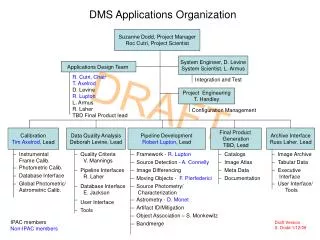
Magnetic shielding - top Incident beam
Cut from closest interference • Plate on ARCS side makes matters worse • Rounded edges don’t help in far field • 5cm is ~ 200 layers of electric steel • Need IDT’s opinion on the need for fields
Summary • Progressing on SEQUOIA • Guide vendor selected • Detector Vessel and Sample Vessel out for bid • Shielding, Fermi chopper, and T0 chopper to go out for bid in the next 6 months • In monolith components installed • A workable sample area has been proposed • T0 chopper allows crystal alignment • Magnetic shielding – We need your input