Download
1 / 21
210 likes | 412 Views
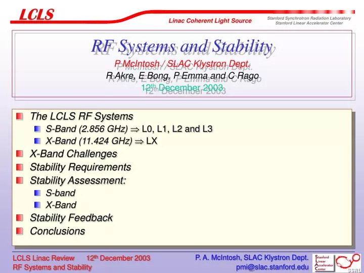
RF Systems and Stability P McIntosh / SLAC Klystron Dept. R Akre, E Bong, P Emma and C Rago 12 th December 2003. The LCLS RF Systems S-Band (2.856 GHz) L0, L1, L2 and L3 X-Band (11.424 GHz) LX X-Band Challenges Stability Requirements Stability Assessment: S-band X-Band

E N D
RF Systems and StabilityP McIntosh / SLAC Klystron Dept.R Akre, E Bong, P Emma and C Rago12th December 2003 • The LCLS RF Systems • S-Band (2.856 GHz) L0, L1, L2 and L3 • X-Band (11.424 GHz) LX • X-Band Challenges • Stability Requirements • Stability Assessment: • S-band • X-Band • Stability Feedback • Conclusions P. A. McIntosh, SLAC Klystron Dept.
LCLS Layout – LINAC RF Systems 250 MeV z 0.19 mm 1.6 % 4.54 GeV z 0.022 mm 0.71 % 14.1 GeV z 0.022 mm 0.01 % 6 MeV z 0.83 mm 0.05 % 135 MeV z 0.83 mm 0.10 % Linac-X L =0.6 m rf= -160 rf gun Linac-1 L 9 m rf -25° Linac-2 L 330 m rf -41° Linac-3 L 550 m rf -10° new Linac-0 L =6 m undulator L =125 m 21-1b 21-1d 21-3b 24-6d 25-1a 30-8c X ...existing linac BC-1 L 6 m R56 -39 mm BC-2 L 22 m R56 -25 mm DL-1 L 12 m R56 0 LTU L =275 m R56 0 research yard SLAC linac tunnel P. A. McIntosh, SLAC Klystron Dept.
S-Band RF System (2.856 GHz) – L0, L1, L2 and L3 • L0 3 x klystrons for individual amplitude and phase control of each accelerating section to optimize control from the RF Gun. • L1 1 x klystron feeding 3 accelerator sections. • L0 and L1 klystrons operated at ~5% below saturation to allow sufficient feedback stability overhead. • LX 1 x XL-4 klystron feeding 1 NLC-type accelerating structure. • L2 26 x klystrons (plus 2 standby) with all but 2 operated in saturation with no amplitude control: • 2 klystrons near the end of L2 will operate unsaturated to provide amplitude feedback at high energy. • Global phase control made with -feedback on final sector in L2 provides precise control of the average L2 phase. • L3 45 klystrons (plus 3 standby) operated in the same mode as L2 for amplitude and phase control. See C Rago’s Talk: RF Waveguide and Structures P. A. McIntosh, SLAC Klystron Dept.
Need for a X-Band RF System • The 60cm long X-band structure is used to linearize the energy-time correlation (or gradient) across each bunch from L0 and L1. • Operates on the negative RF crest to decelerate the beam, reducing the non-linear components of the correlation more efficient compression in BC1 and BC2! • Non-linear correlation components CSR instabilities in the chicanes. • Beam energy is reduced by 18 MeV, from 268 to 250 MeV. • X-band structure accelerating gradient is ~32 MeV/m. • Bunch length compressed from 830 to 190 m c.f. 400 m without the X-band station. See P Emma’s Talk: Accelerator Design P. A. McIntosh, SLAC Klystron Dept.
Compression Without X-Band System After L1 After BC1 P. A. McIntosh, SLAC Klystron Dept.
Compression With X-Band System After L1 After LX After BC1 P. A. McIntosh, SLAC Klystron Dept.
X-Band RF System Parameters P. A. McIntosh, SLAC Klystron Dept.
X-Band RF System Layout • X-Band Klystron • SLAC XL-4 • Structure • SLAC 0.6-m X-Band Structure • Modulator-Pulse Transformer • Existing SLAC Linac Modulator • 19:1 turn ratio Pulse Transformer • Waveguide Distribution • WR293 Penetration Run • Mode Converter • WR100 in Gallery & Housing P. A. McIntosh, SLAC Klystron Dept.
X-Band Component Parameters P. A. McIntosh, SLAC Klystron Dept.
X-Band RF Station Challenges • NLCTA have used X-Band Klystrons for many years to power X-Band Structures. • Stability/reliability issues need to be addressed for LCLS: • No reason to believe the XL4 phase and amplitude sensitivity to modulator stability will be much greater than that of a 5045 klystron. • Tests must be performed to determine if the X-Band system will meet LCLS stability requirements. • NLCTA has not run at 120 Hz: • The reliability of the tubes at 120 Hz needs to be evaluated. • NLCTA runs at 60 Hz with 1.6-s flat top pulses @ 50 MW. • LCLS requires 120 Hz with 0.1-s flat top pulses @ 21 MW. • Reliability no concern if tube run below 30 MW or if modulator rise/fall times are reduced, reducing the average power. • Spare Klystron required to reduce downtime in case of failure. P. A. McIntosh, SLAC Klystron Dept.
X- X-band Stability Requirements rms tolerances at < 10 secs time scale for gaussian bunch distribution P. A. McIntosh, SLAC Klystron Dept.
S-Band Stability • There are 9 klystrons (incl. RF Gun klystron) in the LCLS design that will require RF feedback. • The phase and amplitude of each of the 3 klystrons in L0 and the 5 x S-band klystrons of L1, L2 and L3 must all be held to the stability specifications shown. • Tests show this stability can be maintained over several seconds by the existing systems. • Beyond 2 seconds, feedback will be required to adjust the phase and amplitude of the S-band LINAC systems. P. A. McIntosh, SLAC Klystron Dept.
Phase Jitter 21-6 and 21-7 (L2) – Short Term Changes Pulse-pulse variation over 2 secs (@ 30Hz sampling and operation) 2 = 0.037o 2 = 0.057o Requirement: 2 = 0.07o P. A. McIntosh, SLAC Klystron Dept.
Amplitude Jitter 21-6 and 21-7 (L2) – Short Term Changes Pulse-pulse variation over 2 secs (@ 30Hz sampling and operation) V2/V2 = 0.026% V2/V2 = 0.036% Requirement: V2/V2 = 0.1% P. A. McIntosh, SLAC Klystron Dept.
Phase Jitter 21-6 and 21-7 (L2) – Long Term Drifts Pulse-pulse variation over 14 mins (@ 30Hz operation and 0.6Hz sampling) 2 = 1.2o 2 = 1.25o Requirement: 2 = 0.07o P. A. McIntosh, SLAC Klystron Dept.
Amplitude Jitter 21-6 and 21-7 (L2) – Long Term Drifts Pulse-pulse variation over 14 mins (@ 30Hz operation and 0.6Hz sampling) V2/V2 = 0.2% V2/V2 = 0.43% Requirement: V2/V2 = 0.1% P. A. McIntosh, SLAC Klystron Dept.
X-Band Stability • NLCTA modulator voltage stability ~ 0.01%. • Nominal operating voltage of 350 kV 35 V variation • XL-4 phase stability vs beam voltage = 0.0033o/V • XL-4 phase stability then becomes ~ 0.12o without feedback! • L2 modulators are currently regulating to better than 0.01%! • NLCTA structure temperature tuning stability ~200 kHz/oC • Need to regulate structure temperature to 0.025oC • detuning 10 kHz • Phase variation = xs = 0.36o (for filling time s = 100 ns) without feedback! • Estimate for X-band system phase stability h = 0.48o • LCLS requirement is h = 0.50o P. A. McIntosh, SLAC Klystron Dept.
S-Band Stability Feedback • Changes in phase or amplitude of the LINAC systems, result in a change in energy and bunch length. • All klystrons will use the existing phase and amplitude control systems to limit each klystron phase and amplitude to within 10o and 2% respectively for long term drift compensation. • Additional feedback controls will require: • Energy of the beam is measured via existing BPMs located in high dispersion regions. • A Bunch Length Monitor (BLM): synchrotron radiation monitor, RF cavity, or some other device to measure bunch length – risk associated with using z as feedback parameter: • see P Krejcik’s Talk: Diagnostics and Controls P. A. McIntosh, SLAC Klystron Dept.
S-Band Stability Feedback (cont’d) • Not possible to get accurate measurement of the phase in an accelerating structure as seen by the beam from the input or output RF alone – due to the structure temp. vs variations. • May be possible if the input phase, output phase, and temperature of the structures are known in L0 and L1. • These first 5 accelerating klystrons will have phase and amplitude measurements at the input and output of the structures: • Structures will also include thermocouples to measure temperature fluctuations. Without Beam-Based feedback, the above controls will not achieve LCLS requirements for long term stability! P. A. McIntosh, SLAC Klystron Dept.
Feedback Schematic • A new RF feedback system will use these inputs to actuate additional phase and amplitude control units to adjust the RF to keep the beam to within LCLS specifications. Beam Based Parameters P. A. McIntosh, SLAC Klystron Dept.
Conclusions • S-Band RF System: • Short term LCLS phase and amplitude stability requirements look achievable now, but for long term stability requires feedback. • New feedback reacts to structure input/output amplitude and phase, global temperature variations and beam-based parameters to control to 0.08% and 0.07o LCLS margins. • X-Band RF System: • Required for improved bunch compression. • Phase and amplitude stability requirements not as tight as the S-band system phase stability of 0.5o looks achievable. • 120Hz operation of XL-4 klystron not proven, but providing power is limited to <30 MW then don’t anticipate any reliability problems. P. A. McIntosh, SLAC Klystron Dept.