Download
1 / 16
160 likes | 338 Views
Optics in Internet Routers. Mark Horowitz, Nick McKeown, Olav Solgaard, David Miller Stanford University http://klamath.stanford.edu/or. Why We Need Faster Routers. To prevent routers from becoming the bottleneck. Packet processing Power. Link Speed. 10000. 1000.

E N D
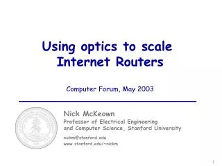
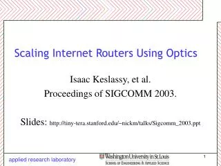
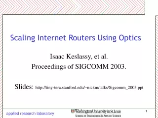
Optics in Internet Routers Mark Horowitz, Nick McKeown, Olav Solgaard, David Miller Stanford University http://klamath.stanford.edu/or
Why We Need Faster Routers • To prevent routers from becoming the bottleneck Packet processing Power Link Speed 10000 1000 2x / 18 months 2x / 7 months 100 Fiber Capacity (Gbit/s) 10 1 1985 1990 1995 2000 0,1 TDM DWDM Source: SPEC95Int & David Miller, Stanford
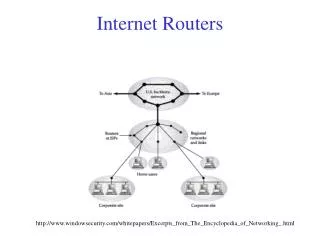
Fast (Large) Routers Big POPs need big routers POP with large routers POP with smaller routers Interfaces: Price >$100k, Power > 400W It is common for 50-60% of interfaces to be for interconnection within the POP Industry trend is towards large, single router per POP
All optical IP routers are infeasible today • A router is a packet-switch,and therefore requires • A switch fabric • Per-packet address lookup • Large buffers for times of congestion • Address lookup and buffering are infeasible using optics presently • A typical 10 Gb/s router linecard has 30 Mgates and 2.5 Gbits of memory • Research Problem • How to optimize the architecture of a router that uses an optical switch fabric?
100 Tb/s Optical Router 100 Tb/s Optical Router • Collaboration • 4 Stanford professors (M. Horowitz, N. McKeown, D. Miller and O. Solgaard), and their groups • Objective • To determine the best way to incorporate optics into routers • Push technology hard to expose new issues • Photonics, Electronics, System design • Motivating example: The design of a 100 Tb/s Internet router • Challenging but not impossible (~100x current systems) • It identifies some interesting research problems
100 Tb/s Router Optical Switch Electronic Linecard #1 Electronic Linecard #625 160- 320Gb/s 160- 320Gb/s 40Gb/s • Line termination • IP packet processing • Packet buffering • Line termination • IP packet processing • Packet buffering 40Gb/s 160Gb/s 40Gb/s Arbitration Request 40Gb/s Grant (100Tb/s = 625 * 160Gb/s)
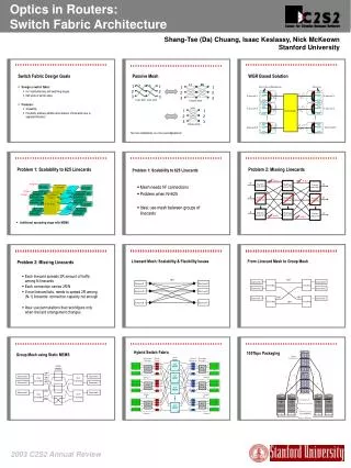
Research Problems • Linecard • Memory bottleneck: Address lookup and packet buffering • Architecture • Arbitration: Computation complexity • Switch Fabric • Optics: Fabric scalability and speed • Electronics: Switch control and link electronics • Packaging: Three surface problem
160Gb/s Linecard: Packet Buffering DRAM DRAM DRAM 160 Gb/s 160 Gb/s Queue Manager SRAM • Problem • Packet buffer needs density of DRAM (40 Gbits) and speed of SRAM (2ns per packet) • Solution • Hybrid solution uses on-chip SRAM and off-chip DRAM • Identified optimal algorithms that minimize size of SRAM (12 Mbits) • Precisely emulates behavior of 40 Gbit, 2ns SRAM [klamath.stanford.edu/~sundaes/Papers/ieeehpsr2001.pdf]
Architecture: The Arbitration Problem • A packet switch fabric is reconfigured for every packet transfer • At 160Gb/s, a new IP packet can arrive every 2ns • The configuration is picked to maximize throughput and not waste capacity • Known algorithms are too slow Our solution is to eliminate the arbitration
1 1 1 N N N Two-Stage Switch External Inputs Internal Inputs External Outputs Spanning Set of Permutations Spanning Set of Permutations Recently shown to maximize throughput [C.S.Chang et al.: http://www.ee.nthu.edu.tw/~cschang/PartI.pdf]
2 1 2 1 1 1 1 N N N Problem: Unbounded Mis-sequencing External Inputs Internal Inputs External Outputs Spanning Set of Permutations Spanning Set of Permutations • We have developed an algorithm to • Keep packets ordered and • Guarantee a delay bound within the optimum [Infocom’02: klamath.stanford.edu/~keslassy/download/infocom02_two_stage.pdf]
An Optical Two-stage Switch Linecards Lookup Phase 1 Buffer 1 Lookup Buffer 2 Phase 2 Lookup Buffer Idea: use a single-stage twice 3
Input 1 Output 1 1 1 Output 2 Input 2 Output m Input m Input 1 Output 1 2 2 Output 2 Input 2 Output m Input m Input 1 Output 1 n n Output 2 Input 2 Output m Input m Cascaded Wavelength Switches • mn x mn switching fabric • 2n building blocks • Supports spanning set of permutations
Output 1 Output 2 Output n Input 1 Input 2 l1 l1, l2, …, ln l2 l1, l2, …, ln Input m l1, l2, …, ln ln Power Combiner Wavelength Demultiplexer Building Block: Wavelength Switch • m-Input and n-Output • Switching by wavelength selection of tunable lasers • Optical amplifier (EDFA) can be included to reduce loss
l1 Input 1 Output 1 l2 Input 2 Output 2 Output m ln Input n Tunable Filters Power Divider Wavelength Multiplexer Wavelength Switch:Receiver Side • n-Input and m-Output • Tunable optical filtersare key components
CMOS Optical Receiver • A 1.6Gb/s, 3mW Integrating CMOS Optical Receiver with AlGaAs Photo-Detectors • Standard CMOS Electronics with flip-chip bonded optical devices • Removes the trans-impedance amplifier to reduce power and improve bit-rate. • Enables dense arrays of receivers and transmitters on chip Arrays of Optoelectronic Transceivers