Download
1 / 37
390 likes | 611 Views
Integration of MBSE and Virtual Engineering for Detailed Design. Presented by: Akshay Kande Advisor: Dr. Steven Corns Missouri University of Science & Technology. Towards Creating an Integrated Development Environment for Engineering Systems. Virtual Engineering.

E N D
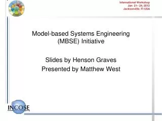
Integration of MBSE and Virtual Engineering for Detailed Design Presented by: Akshay Kande Advisor: Dr. Steven Corns Missouri University of Science & Technology
Towards Creating an Integrated Development Environment for Engineering Systems Virtual Engineering Model Based Systems Engineering Systems Engineering Complexity
Objectives • Creating a seamless integration of MBSE and detail design tools to • Manage complexity • Help engineers to make informed decisions • Execute engineering models • Understand potential impacts of changing design parameters
Complexity A property by which behavior of elements gets interconnected in such a way that changes made no longer have effects limited to the local area. Latin word plexus – interwoven
Complexity and Systems Engineering • Later was first introduced to satisfy the demands of systems with • increased performance capabilities • reduced cost • Short development time Systems engineering provides a systematic way to manage complex engineering ventures that consists of highly interconnected subsystems
Systems Engineering Process Effective management of Information flow remains one of the key drivers to the success of the systems engineering activity Sanford Friedenthal, Alan Moore, Rick Steiner, A Practical Guide to SysML: The Systems Modeling Language, Morgan Kaufmann Publishers Inc., San Francisco, CA, 2008.
Traditional Approach Requirements System Functions System Design ……. ……. Document Centric Method
Drawbacks • Large collection of individual documents • Difficulty in maintaining consistency • Extraction of relevant information becomes cumbersome • Difficulty to maintain the most updated document
Model Based Systems Engineering INCOSE defines MBSE as, “Formalized application of modeling to support system requirements, design, analysis, verification, and validation activities beginning in the conceptual design phase and continuing throughout the development and later life cycle phases.”
Model Based Systems Engineering In MBSE, models are used to represent • Structural • Operational • Behavioral characteristics of the system being developed
MBSE (Contd.) • Typical MBSE environment consists of following elements • Modeling Language • Modeling Tool
Systems Modeling Language • General purpose modeling language • Developed by the OMG group • Supports model based systems engineering • Extension of Unified Modeling Language(UML) • Supports design, analysis, verification and validation of systems
SysML Diagram Types http://www.omgsysml.org/
Systems Modeling Language • Limitations • Models lack self execution capability • Dependence on external analysis tools • Lack of executable architecture framework
Extending Capabilities Design & Analysis tools • How do we provide the detailed design & analysis capabilities? • How do we enhance decision making?
Proposed Solution • Virtual Engineering • A means for creating a representation of physical system in a computer generated virtual environment • Gives designers the ability to interrogate a system and observe how it reacts to design changes • Provides an accessible visual format to present information in a manner that is of value to all the stakeholders
VE-Suite • Open-source virtual engineering software package • Developed for engineering analysis and design of complex systems in a virtual environment • Provides a highly integrated virtual environment where the results of engineering models such as • CAD, • Finite element analysis, • Computational fluid dynamics can be displayed in a single environment
VE-Suite Architecture User Interface Graphical engine Computational unit
Methodology VE-Suite Model Structure Composition
Methodology (Contd.) Analysis Model Structure in SysML
Modeling Methodology Profile is a mechanism to extend capabilities of modeling languages to suit domain requirements
Modeling Methodology MBSE Tool Simulation block Constraint block System Structure Design parameters and time constraints Parametric equations CAD model References VE-UI VE-Unit VE-GP The model organization created in the MBSE tool allows the code to be readily available for compilation to create the Plugins for VE-Suite.
Example Model • Fermentor: Used in the bio-processing industry for producing compounds such as citric acid and ethanol Layout of the Fermentor model
Model development in SysML Value properties that depict the quantifiable characteristics of the blocks. These quantities also represent the input and outputparameters considered in the experiment.
Defining Constraints for Analysis Constraints used for calculating the citric acid concentration defined using SysML construct
Parametric Model Parametric diagram relating structural and simulation properties
Adding VE Models • Three main VE-Suite Components for fermentor in MBSE environment: • FermentorUI • FermentorUnit • FermentorGP Each VE-Suite module in the MBSE environment is composed of operations specific to the Plugin it has to create
Using CAD models • Architecture of Computer Aided Design (CAD) models is used to represent the system being developed • Part properties of the fermentor system model are referenced with individual CAD files that represent their structure • Done using an UML operation to read data from the CAD file using OSG function
Discussion and Closure • Use of model based engineering adds modularity, reusability and easy maintainability of design information • SysML covers varying aspects of systems engineering activity by providing easy to use graphical constructs • A complete model traceability can be maintained using relationship semantics However, lack of self execution capabilities renders it to rely on external analysis tools for detail design
Virtual Systems Modeling Approach • Potential of SysML to manage information complexity can be used in conjunction with executable detailed design models • Enhanced decision making capabilities • System performance can be tested for different combination of parameter values • Maintain consistency while executing analysis models
Future Work • The example model defines the creation of a user defined computation unit which is one among the numerous capabilities that VE platform offers. Future work shall be • To use high fidelity models in conjunction with systems engineering data • To streamline the integration process by porting the auto-code generation API into a VE-Suite interface