Download
1 / 1
20 likes | 186 Views
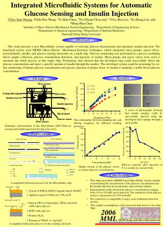
Microfluidic System for Automatic Cell Culture. D0. D3. D1. D4. Unit: mm. Trypsin reservoir. Waste reservoir. Microvalve. Air inlet. Flow rate ( μ l/min). 15. D2. D5. Micropump. 40. (a). Cell culture area. Back pressure (mm-H 2 O). (b). Microchannel. PBS reservoir.

E N D
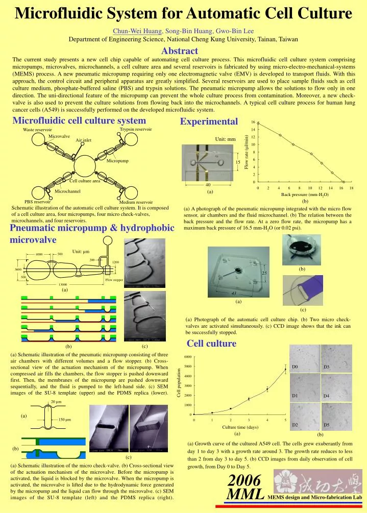
Microfluidic System for Automatic Cell Culture D0 D3 D1 D4 Unit: mm Trypsin reservoir Waste reservoir Microvalve Air inlet Flow rate (μl/min) 15 D2 D5 Micropump 40 (a) Cell culture area Back pressure (mm-H2O) (b) Microchannel PBS reservoir Medium reservoir Unit: µm 25 500 4000 200 1200 3600 43 500 (a) Flow stopper 13000 (a) (b) (c) (c) (b) Cell population 20 µm Culture time (days) (a) (a) (b) 150 µm (b) (c) Chun-Wei Huang, Song-Bin Huang, Gwo-Bin Lee Department of Engineering Science, National Cheng Kung University, Tainan, Taiwan Abstract The current study presents a new cell chip capable of automating cell culture process. This microfluidic cell culture system comprising micropumps, microvalves, microchannels, a cell culture area and several reservoirs is fabricated by using micro-electro-mechanical-systems (MEMS) process. A new pneumatic micropump requiring only one electromagnetic valve (EMV) is developed to transport fluids. With this approach, the control circuit and peripheral apparatus are greatly simplified. Several reservoirs are used to place sample fluids such as cell culture medium, phosphate-buffered saline (PBS) and trypsin solutions. The pneumatic micropump allows the solutions to flow only in one direction. The uni-directional feature of the micropump can prevent the whole culture process from contamination. Moreover, a new check-valve is also used to prevent the culture solutions from flowing back into the microchannels. A typical cell culture process for human lung cancer cells (A549) is successfully performed on the developed microfluidic system. Microfluidic cell culture system Experimental Schematic illustration of the automatic cell culture system. It is composed of a cell culture area, four micropumps, four micro check-valves, microchannels, and four reservoirs. (a) A photograph of the pneumatic micropump integrated with the micro flow sensor, air chambers and the fluid microchannel. (b) The relation between the back pressure and the flow rate. At a zero flow rate, the micropump has a maximum back pressure of 16.5 mm-H2O (or 0.02 psi). Pneumatic micropump & hydrophobic microvalve (a) Photograph of the automatic cell culture chip. (b) Two micro check-valves are activated simultaneously. (c) CCD image shows that the ink can be successfully stopped. Cell culture (a) Schematic illustration of the pneumatic micropump consisting of three air chambers with different volumes and a flow stopper. (b) Cross-sectional view of the actuation mechanism of the micropump. When compressed air fills the chambers, the flow stopper is pushed downward first. Then, the membranes of the micropump are pushed downward sequentially, and the fluid is pumped to the left-hand side. (c) SEM images of the SU-8 template (upper) and the PDMS replica (lower). (a) Growth curve of the cultured A549 cell. The cells grew exuberantly from day 1 to day 3 with a growth rate around 3. The growth rate reduces to less than 2 from day 3 to day 5. (b) CCD images from daily observation of cell growth, from Day 0 to Day 5. (a) Schematic illustration of the micro check-valve. (b) Cross-sectional view of the actuation mechanism of the microvalve. Before the micropump is activated, the liquid is blocked by the microvalve. When the micropump is activated, the microvalve is lifted due to the hydrodynamic force generated by the micropump and the liquid can flow through the microvalve. (c) SEM images of the SU-8 template (left) and the PDMS replica (right). 2006 MML MEMS design and Micro-fabrication Lab