Download
1 / 20
200 likes | 361 Views
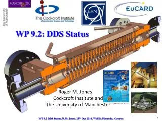
DDS design status Task 9.2-Sub-task 2 . Alessandro D’Elia on behalf of Roger M. Jones. CLIC_DDS_A. PRELIMINARY. CLIC_DDS_B. Analysis of structures with different phase advances: 5 /9 and 5 /6 in comparison with the standard 2 /3

E N D
DDS design statusTask 9.2-Sub-task 2 Alessandro D’Elia on behalf of Roger M. Jones
CLIC_DDS_A PRELIMINARY
CLIC_DDS_B • Analysis of structures with different phase advances: 5/9 and 5/6 in comparison with the standard 2/3 • The basic idea is to explore if we can find a compromise between a possible larger bandwidth (5/9) to the detriment of higher kicks or lower kicks (5/6) to the detriment of a smaller bandwidth New Design: better but still not in the limits
2/3 Linear tapering To efficiently damp the first trailing bunch staying this detuning (~2.5GHz), we would need a <Q>~14
5/9 Linear tapering Quite high kicks and a very high-Q resonance in the 5th-7th bands
First Cell 5pi/6 Mid Cell Last Cell
5pi/6 Linear tapering Last Cell <Qdip>=495 <Qdip>=184 Q=1438 (not yet saturated)
First Dipole Wake Linear tapering <Qdip>=382 dipole kick=61 V/pc mm m Even if we get rid of the “higher” higher order modes, we are not able to efficiently damp first trailing bunches staying this detuning (~2.2GHz) and this damping (<Q>~382)
Change Manifold Width If I change WGW: Dipole distribution stays the same but Manifold mode distribution will become higher and will “squash” against dipoles. This will move back the avoided crossing region. Drawback is a reduction of avoided crossing and a slight reduction of the fsyn of the cell. WGW=5mm Light Line WGW=6mm Dipole Manifold First Cell, WGW=5mm But…
Tapered Manifold Width First Cell Last Cell
Linear tapering Previous wake
1st Cell E-Field@27GHz-7th Band
Mid Cell E-Field@25.2GHz-5th Band
Last Cell E-Field@24.88GHz-5th Band
Brillouin Diagram–EField 1st Cell Mid Cell 7th Band Coupling 7th Band 6th Band Hybrid 6th Band 5th Band 5th Band Last Cell 7th Band No Coupling 6th Band 5th Band Dangerous 5th Band Last Cell
Conclusions • 5/9 (100 phase advance) structure exhibits, as expected, higher kicks than 2/3 without any improvement in bandwidth (only 30MHz!) • 5/6: • Pulse temperature rise limits the aperture of first iris to be lower than 4.3mm • This implies that in order to have a reasonable bandwidth last iris aperture must be well below 3mm • Iris aperture lower than 3mm exhibits enhancement in the kicks of 5th-7thband • This enhancement is difficult to cure • From this analysis it comes out that: • With <Eacc>=100MV/m it looks very difficult to meet at the same time both CLIC beam dynamics (long range wake) and RF constraints • For CLIC_Zero with <Eacc>=80MV/m there could be some margin • Nevertheless, CLIC_DDS_A prototype is (almost) ready to be tested: breakdown measurements will be crucial for DDS • Started to apply DDS design to other facilities (ELI) and the results are very promising