Download
1 / 21
210 likes | 459 Views
Linac4. M. Vretenar for the Linac4 design team HHH Workshop – 24.11.2008. Linac4 – historical background. 1996: first proposal of a Superconducting Proton Linac (SPL) at CERN, using the LEP accelerating system (cavities + RF) for a high power linac, with injection into the PS at 2 GeV.

E N D
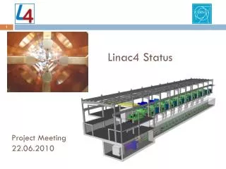
Linac4 M. Vretenar for the Linac4 design team HHH Workshop – 24.11.2008
Linac4 – historical background 1996: first proposal of a Superconducting Proton Linac (SPL) at CERN, using the LEP accelerating system (cavities + RF) for a high power linac, with injection into the PS at 2 GeV. 2000: SPL “Conceptual Design Study”. 2001: idea to build in a first stage the warm part of the SPL (120 MeV) in the old PS South Hall and use it to inject H− into the PSB, improving the beam brightness in the PS complex. 2003: energy up to 160 MeV, called “Linac4” (4th linac to be built at CERN) 2004: start Linac4 R&D, - started CARE Activity on high-intensity linacs (HIPPI), for (2004-08). - Agreements with France (IPHI RFQ) and with ISTC (prototypes in Russia). 2006: first draft of “White Paper”, including Linac4 construction in the frame of LHC Upgrade plans. Linac4 Technical Design Report issued December 2006. 2007: define a new location for Linac4, permitting extension to LP (Low-power)-SPL. Approval of White Paper by CERN Council (June). 2008: Official start of the project.
Linac4 on the CERN site Linac4 will replace Linac2 (50 MeV) as injector to the PSB. It will be built at the place of “Mount Citron”, made in the 50’s with the excavation materials of the PS. Position and orientation allow a future extension to the SPL. PS PSB PS2 - SPS Transfer line Future SPL Present 50 MeV Linac2 Linac4
Linac4: 3 modes of operation Linac4 is designed to operate in 3 different modes: Injector to PS Booster(2013-2017?): 1.1 Hz, 40 mA, 400 ms. Injector to Low Power-SPL(2018- ?): 2 Hz, 20 mA, 1.2 ms only minor upgrade (few power supplies) Injector to High Power-SPL(>2020 ?): 50 Hz, 40 mA, 1.2 ms max. important upgrade (RF modulators, power supplies, cooling, etc.) Main consequences on the design: Shielding dimensioned for the SPL high beam power operation (1 W/m beam loss). Accelerating structures and klystrons dimensioned for high duty operation. Power supplies, electronics and infrastructure (water, electricity) dimensioned only for low beam power operation (PSB, LP-SPL). Space provided at the end of the linac for the connection to the SPL
Linac4 Parameters H− particles + higher injection energy (160/50 MeV, factor 2 in bg2) same tune shift in PSB with twice the intensity. Ion species H− Output Energy 160 MeV Bunch Frequency 352.2 MHz Max. Rep. Rate 2 Hz Max. Beam Pulse Length 1.2 ms Max. Beam Duty Cycle 0.24 % Chopper Beam-on Factor 65 % Chopping scheme: 222 transmitted /133 empty buckets Source current 80 mA RFQ output current 70 mA Linac pulse current 40 mA N. particles per pulse 1.0 × 10¹⁴ Transverse emittance 0.4 p mm mrad Max. rep. rate for accelerating structures 50 Hz Re-use 352 MHz LEP RF components: klystrons, waveguides, circulators. Chopping at low energy to reduce beam loss at PSB. • Structures and klystrons dimensioned for 50 Hz • Power supplies and electronics dimensioned for 2 Hz, 1.2 ms pulse.
Linac4 for the PS Booster (PSB) Bottleneck for higher brightness at PSB injection: Incoherent space charge tune shift dominates injection process. • Present scheme LHC nominal beam in PS with 3x1x2 PSB bunches (3 rings x 1 bunch x 2 batches), at the limit of what can be achieved by the injectors (1.2 1011 ppb). • New scheme with Linac4 increase bunch density in the PSB by a factor 2, in order to: • Make nominal LHC beam in single batch (simpler operation). • Gain a margin for reaching the ultimate LHC bunch population (50% higher) in single or double batch. • Injection energy from 50 to 160 MeV Increase in bg2 by factor 2 same tune shift at injection (DQ I/bg2) with twice the intensity. • Additional advantages with Linac4: • Modern H− charge exchange injection. • Chopper at low energy remove linac bunches at the edges of PSB longitudinal acceptance reduce loss and increase flexibility at capture in PSB. • More features to reduce beam loss (collimation, longitudinal painting). • Modern machine, less operational concerns (Linac2 vacuum, etc.)
Linac4 challenges • First challenge of Linac4 is RELIABILITY: must operate ~6000 hours/year with a fault rate comparable to Linac2, ~1.5% of scheduled beam time. • Control of transverse and longitudinal EMITTANCE GROWTH is of paramount importance for clean PSB and SPL injection. • Careful LOSS CONTROL to prepare for the SPL mode of operation uncontrolled beam loss <1 W/m in SPL mode <0.1 W/m in PSB injection mode (at 160 MeV, 1.5*10-5/m loss rate). • Keep the COST of the machine within what is acceptable in the critical post-LHC period.
Linac4 Layout 45keV 3MeV 3MeV 50MeV 102MeV 160MeV H- RFQ CHOPPER DTL CCDTL PIMS Drift Tube Linac 352 MHz 18.7 m 3 tanks 3 klystrons 4 MW 111 PMQs Cell-Coupled Drift Tube Linac 352 MHz 25 m 21 tanks 7 klystrons 6.5 MW 21 EMQuads Pi-Mode Structure 352 MHz 22 m 12 tanks 8 klystrons ~12 MW 12 EMQuads RF volume source (DESY type) Radio Frequency Quadrupole 352 MHz 3 m 1 Klystron 540 kW Chopper Line 352 MHz 3.6 m 11 EMquad 3 cavities Total Linac4: 80 m, 18 klystrons 4 different structures, (RFQ, DTL, CCDTL, PIMS) RF Duty cycle: 0.1% phase 1 (Linac4) 3-4% phase 3 (HP-SPL) Ion current: 40 mA (avg. in pulse), 65 mA (bunch)
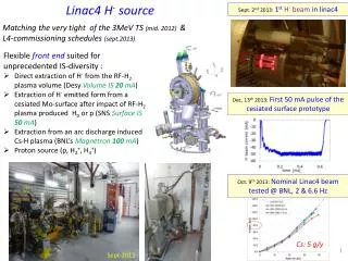
The 3 MeV Test Stand RFQ source chopper line • In construction in the South Hall extension. • - H- source (2008) • LEBT (2008-09) • RFQ (February 2010) • Chopper line (2008) • Diagnostics line (2010) • Infrastructure (1 LEP Klystron, pulsed modulator, etc.) - ready • In the front end are concentrated some of the most challenging technologies in linacs, and this is where the beam quality is generated. Early understanding and optimisation of front-end is fundamental for a linac project. diagnostics line klystron modulator
Linac4 accelerating structures Linac4 accelerates H- ions up to 160 MeV energy: • in about 80 m length • using 4 different accelerating structures, all at 352 MHz • the Radio-Frequency power is produced by 19 klystrons • focusing of the beam is provided by 111 Permanent Magnet Quadrupoles and 33 Electromagnetic Quadrupoles PIMS A 70 m long transfer line connects to the existing line Linac2 - PS Booster
Linac4 accelerating structures DTL CCDTL PIMS 7-cell cavities in p-mode. With respect to the SCL, the PIMS : • has 5 times less cells (less machining time and cost). • needs about the same quantity of copper. • allows a simpler tuning (7 cells instead of >100, dummy tuners). • allows standardisation of the Linac4 frequency to 352 MHz. • has only about 12% less shunt impedance. Modules of 3 SDTL-type cavities with 2 drift tubes, coupled by 2 coupling cells. • Easy access and alignment of electromagnetic quadrupoles. • Relaxed tolerances on drift tube alignment. Conventional DTL structure with: • PMQs in vacuum inside drift tube. • no drift tube adjustment after installation.
Linac4 Beam Dynamics Smooth beam dynamics design, to minimise emittance growth and losses at high beam power (<1 W/m): 1. Zero current phase advance <90º (avoid resonances) 2. Longitudinal to transverse phase advance ratio 0.5-0.8 (minimise emittance exchange) 3. Smooth variation of transverse and longitudinal phase advance per meter. 4. Sufficient safety margin between beam radius and aperture (>7 rms) Integrated simulations with machine errors, alignment errors and steering correction.
Linac4 Beam – Longitudinal Painting Transfer line to PSB debuncher Longitudinal beam parameters along line and at PSB entrance Energy modulation with last 2 PIMS cavities Painting scheme: linear energy ramp over 10+10 PSB buckets (with low energy chopping limiting sweep to 222 linac bunches)
Linac4 civil engineering Equipment building ground level Linac4 tunnel Linac4-Linac2 transfer line Low-energy injector Access building Pre-integration May – October 2007 Tendering drawings November 2007 – April 2008 Tendering May 2008, Contract to FC September 2008. Start of Civil Engineering Works in October 2008.
Linac4 Groundbreaking 16 October 2008, Linac4 Groundbreaking by CERN Director, R. Aymar
Linac4 Work Breakdown Structure Total of 30 Workpackages
Linac4 Master Plan • End CE works: December 2010 • Installation: 2011 • Linac commissioning: 2012 • Modifications PSB: shut-down 2012/13 (7.5 months) • Beam from PSB: 15.6.2013 White Paper
Linac4 Status (11/2008) • Civil Engineering works started 22.10.2008, delivery of building end 2010. • Safety File submitted to CERN Safety Commission in June 2008. Building approved. • Ion source almost completed, first beam tests end 2008. • 3 MeV Test Stand infrastructure completed. • Prototype modulator tested with LEP klystron in pulsed mode. • Prototypes of accelerating structures tested (CCDTL), being tested (DTL), starting construction (PIMS). Material being ordered, construction of DTL and CCDTL will start in 2009. • Started preparation for large contracts (klystrons, modulators, magnets,…). • Detailed descriptions of Workpackages in preparation, project baseline will be frozen at end 2008. • Advanced negotiations for in-kind contributions with France, Russia (via the ISTC Organisation), Poland, Spain (via ESS-Bilbao), India, Pakistan, Saudi Arabia.