Download
1 / 27
270 likes | 434 Views
ATLAS STRIPS UPGRADE. Mercedes Miñano on behalf of the ATLAS SCT Collaboration 17 September 2009. Outline. LHC vs. sLHC sLHC implications on Silicon Detectors Upgrades to the ATLAS Inner Detector Upgrade ID Layout Radiation Hard Technologies: n- on -p: Miniature sensors :

E N D
ATLAS STRIPS UPGRADE Mercedes Miñano onbehalf of the ATLAS SCT Collaboration 17 September 2009
Outline • LHC vs. sLHC • sLHCimplicationsonSiliconDetectors • Upgradestothe ATLAS Inner Detector • Upgrade ID Layout • RadiationHard Technologies: n-on-p: • Miniaturesensors: • ChargeCollectionunderneutron and protonirradiation • Full DepletionVoltage • LeakageCurrent • Full sizeprototypessensors: • ElectricalCharaterization • Module IntegrationConcepts: • BarrelStave • End-capStave: Petal • Super-Module • Powering • Conclusions
LHC • Designedforluminosity of 1034 cm-2 s-1 • In thefirst 5 years 700fb-1integratedluminosity • FirstCollidingbeamsNovember 2009 • Designedforluminosity of 1035 cm-2 s-1 • SLHC UpgradePlansenvision 3000fb-1 (5 years) • Startingaround 2018-2020 SuperluminousLHC (sLHC)
sLHCImplicationsonSiliconDetectors HIGH OCCUPANCY PARTICLE FLUENCE 1035 cm-2 s-1 1034 cm-2 s-1 Thenumber of collisionswillincreasefrom 20 to 400 per beamcrossing and thetrackmultiplicityisforeseentoabout 14000 (~700 forthe LHC ) Thisimplies a finnergranularityforthedetectorstokeeptheoccupancyacceptablelow. SpeciallyfortheInner Detector (ID) locatedclosetothe LHC interactionregion • Neutrons > 50% at R 25 cm • Strip detector damagelargelyduetoneutrons • Designedfluencesforsensors: • B-layer at 3.7 cm: 2.2 x 10¹⁶ 1MeV n-equivalent /cm2 • Outer pixel layers: 3 x 10¹⁵ 1MeV n-equivalent /cm2 • Middlestriplayer at 38 cm: 1015 1MeV n-equivalent /cm2 • Outerstriplayer at 95 cm: 4 x 10¹⁴ 1MeV n-equivalent /cm2 BarrelSCT Upgrade: 38 < R < 95 cm Thisimplieshigherradiationhardnessforsensors. The ID willbereplaced and technologicallyimproved R&D
Upgradestothe ATLAS Inner Detector • New Detector Layout: Onlysilicon pixel and strips. • Radiationhardtechnologies: n-on-p siliconforplanarstrips. • New Module IntegrationConcepts (low material budget). • New Poweringschemes: Serial Poweringor DC-DC. • New ASIC technologies and fasterreadoutto reduce power in thefront-ends. • DCS (Detector Control System) integratedintothereadoutarchitecture. • New coolingsystemtomaintainsilicontemperaturebelow -20ºC (CO2or C3F8) . • Installation: Limitedaccess time insidethecavern.
UpgradeIDLayout (likelytochange) Pixelswillbe 3-D detector forinnermostlayer (alternativediamond) and n-on-p detector for 3 otherlayers (alternative n-on-n) • Strips: 5 barrellayers: @ 38, 49, 60, 75, and 95 cm • 3 innerlayers: SHORT STRIP LAYERS (24 mm-longstrips) • 2 outerlayers: LONG STRIP LAYERS (96 mm-longstrips) • The 3 outerlayers + theend-capswillreplacethe TRT • Thedesignisexpectedtokeeptheoccupancybelow 1.6% at theinnermostradius. Itisadequate. Pixels Short strips Long Strips
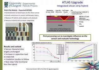
RadiationHard Technologies: n-on-p • p-bulk strip sensors (HPK ATLAS07) are investigated for the ATLAS ID upgrade. Their performance has been evaluated in terms of radiation damage on bulk. • 6 inch (150 mm) wafers • FZ1<100>(~6.7k Ωcm) • FZ2<100>(~6.2k Ωcm) • P-stop and p-stop+p-spray isolation • pitch 74.5 µm, 1280 strips, thickness 320 µm • Miniature sensors (1cm x 1cm) For irradiation studies • Full size prototype sensors (9.75 cm x 9.75 cm) • The sensors are being developed by the R&D collaboration: H. Chen, J. Kierstead, Z. Li, D. Lynn, Brookhaven National Laboratory J.R. Carter, L.B.A. Hommels, D. Robinson, University of Cambridge K. Jakobs, M. Köhler, U. Parzefall, Physikalisches Institut, Universität Freiburg A. Clark, D. Ferrèrre, S. Gonzalez Sevilla, University of Geneva R. Bates, C. Buttar, L. Eklund, V. O'Shea, Dep. of Physics and Astronomy, University of Glasgow Y. Unno, S. Terada, Y. Ikegami, T. Kohriki, Institute of Particle and Nuclear Study, KEK A. Chilingarov, H. Fox, Physics Department, Lancaster University A. A. Affolder, P. P. Allport, H. Brown ,G. Casse, A. Greenall, M. Wormald, Oliver Lodge Laboratory, Dep. of Physics, University of Liverpool V. Cindro, G. Kramberger, I. Mandić, M. Mikuž, Jožef Stefan Institute and Department of Physics, University of Ljubljana I. Gorelov, M. Hoeferkamp, J. Metcalfe, S. Seidel, K. Toms, Dep. of Physics and Astronomy, University of New Mexico Z. Dolezal, P. Kodys, Faculty of Mathematics and Physics, Charles University in Prague. J.Bohm, M.Mikestikova, Academy of Sciences of the Czech Republic C. Betancourt, N. Dawson, V. Fadeyev, M. Gerling, A. A. Grillo, S. Lindgren, P. Maddock, F. Martinez-McKinney, H. F.-W. Sadrozinski, S. Sattari, A. Seiden, J. Von Wilpert, J. Wright, SCIPP, UC Santa Cruz R. French, S. Paganis, D. Tsionou, Dep. of Physics and Astronomy, The University of Sheffield B. DeWilde, R. Maunu, D. Puldon, R. McCarthy, D. Schamberger, Dep. of Physics and Astronomy, Stony Brook University K. Hara, N. Hamasaki, H. Hatano, S. Mitsui, M. Yamada, School of Pure and Applied Sciences, University of Tsukuba M. Miñano, C. García, C. Lacasta, S. Martíi Garcia, IFIC (Centro Mixto CSIC-UVEG) Y.Unno, KEK
MiniatureSensors: ChargeCollection Pre-Irradiation Good agreement between sites/systems. Systematic differences under control. ATLAS Institutes involved: • Valencia uses Beetle based system (MPV charge, analogue data, 25ns shaping time) • Ljubljana and Liverpool use SCT128A based system (MPV charge, analogue data, 25ns shaping time) • Tsukuba/KEK uses a CAMAC 4-ch system with discrete amps (MPV charge, analogue data, 20ns PT) • UC-Santa Cruz uses PTSM based system (Median charge, binary data, 100 ns shaping time)
NeutronIrradiation 5 x 10¹⁴ n /cm2 1 x 10¹⁵ n /cm2 • Ljubljana and Tsukuba/KEK annealedfor 80 minutes at 60ºC • CCE increases by ~25%+/-10% • Liverpool and Valencia do notanneal (withannealingcorrection i.e. CCE reduced by -20%+/-10%) Good!
ProtonIrradiation 1.3 x 10¹⁵neq /cm2 6 x 10¹⁴neq /cm2 • Ljubljana and Tsukuba/KEK annealedfor 80 minutes at 60ºC • CCE increases by ~25%+/-10% • Liverpool and Valencia do notanneal (withannealingcorrection i.e. CCE reduced by -20%+/-10%) Good!
N-on-P FZ Irradiations(HPK and Micronsensors) Micron data from A. Affolder, P.P. Allport & G. Casse, to be published in the proceedings of TIPP09. • Performance of n-on-p FZ sensors produced at Micron and Hamamatsu are the same after all measured irradiation sources. HPK data shown from all sites. Pion irradiation measurements corrected for annealing during run.
Full DepletionVoltageEvaluation Series Sensors FZ1 • Protons: • FDV~700V @1015 cm-2 • Neutrons: • FDV~800V • @ 5 x 1014 cm-2 operation in partial depletion is foreseen K. Hara et al., "Testing of bulk radiation damage of n-in-p silicon sensor for very high radiation environment“ , 7th International “Hiroshima” Symposium on the Development and Applications of Semiconductor Tracking Detectors.
Full Size Prototype Sensors: Electrical Characterization ATLAS institutes involved: • University of Cambridge 2 sensors: W15, W16 • Stony Brook University 9 sensors: W19, W21-23, W25-29 • Institute of Physics and Charles University, Prague 6 sensors: W32, W33, W35, W37, W38, W39 • University of Geneva 2 sensors: W17, W18 Total number of testedsensors: 19 • ATLAS07 Full SizeSensors • 9.75 cm x 9.75 cm • 4 segments: • twowith “axial” strips. 74.5 µm pitch • twowith “stereo” strips. 74.4 µm pitch, 40mrad
BiasScan • No microdischargeswithexceptionone sensor (Vbd~420V). • Sensors satisfy the ATLAS07 Technical Specification (<200um @ 600V) • IV scan was repeated after bias scan and strip scan. • Current was usually higher by 10%- 20% and breakdown for 2 sensors at ~380V. • Estimatedvalues of Vdep: • 6 sensors(Prague) 199-203V • 2 sensors(Cambridge) 235-245V • Alltestedsensorssatisfyspecifications:Vdep < 500V . . .
StripScan . . . All tested sensors Cint ~ 0.75-0.80 pF/cm < 1.1 pF/cm (ATLAS specification) Cint/strip = 1.86pF/strip Measurements taken on central strip with either neighbour grounded. Including next-to-neighbours results in 10-15% higher readings. For 5 sensors Ccpl = 66-68pF/strip ATLAS07 Specification: Ccpl/strip>47.6pF Strip length =2.38cm Rbias=1.30MΩ -1.45MΩ ATLAS07 Specification: Rbias=1.5±0.5MΩ
Module IntegrationConcepts: Stave • Hybridgluedtosensors. Thesegluedto bus tape. Thisgluedtocoolingsubstrate. Resultsagreewith ABCD performance 60 cm, 9 cm strip, 4 chips wide Stave-06 Strip Stave from LBNL 1 m, 3 cm strip, 6 chips wide Stave-07 • Individual hybrids /modules workwellelectrically. Goodnoise performance. All are 900e- • Tested 6 module onstavewith ABCD chips. Serial Poweringlines. • Workingongoing Under Construction: 1.2 m, 2.5 cm strip, 10 chips wide (20 chips/hybrid) 1st prototype module from Liverpool • P-typesensors • ABCN25 chips • KaptonHybrid • Embedded Bus Cable • Stavemechanicalcore • C.Haber (LBL) Stave-09
Module Integration Concept: Petal • Follows quite closelythebarrelstave concept C.Lacasta (IFIC,Valencia) • Thermalsimulationsto explore thebehaviour at criticalpoints: • Assumed -30ºC coolanttemperature (-27ºC onthereturn pipe) • Thesimulationresults show thatthetemperatureonsensorsiswithin safety range (tobeconfirmedwithprototypes) . • 2 carbonfacings + Honeycombsandwichcore • Independent e-services + Bus Cable • Independent C02 cooling pipe • petalsurface: 830 cm2 • 5 disks oneachend-cap • 32 petals/disk (16 oneachside) • 6 different detector typesmountedonpetal • 9 differenthybridtypes • 116 chips/petal Doublesided Simulations of a disk. Issues: Layout, modularity, powering
Alternative module designwithhighermodularity: Super-module • 1) Build individual modules: • Doublesided module • 2 silicon (short) microstripsensors: n+-on-p, 10x10 cm2 • 4 bridgedhybridswith ABCN asicseach • 2) Insert modules into a frame: Super-module • (Basedon SCT experience) • 2 proposalsfor module integrationintocylinders: • Lateral insertion (KEK): Installation of theSuper-Modules, cylinderbycylinder • End-insertion (Geneva): Barrel structures can be assembled before the Super-Modules are integrated . Longitudinal Mounting CircumferentialMounting
Powering Current ID Therequiredhighgranularitysupposes x5 channels and x5 cables in thesamespace!!! New options in powering (not individual powering)
24i i PoweringSchemes • Severaloptionsonpowering: DC/DC or serial. • Cannothave individual module powering toomuch material and no space. • Requirements: Highpowerefficiency, lownoise, safety (overcurrent, overvoltage, overtemperature). Serial Powering • Serial Powering scheme has been shown to perform well on 6 and 30 module staves (Stave06,Stave07) • Excellentnoise performances • • Current issues: • Protectionschemes (shuntregulators) possibleintegrationinto FE chips • Customcurrentsource • DC/DC scheme: • Only 1 power line/stave (10-12V) • • Distribution with 2 conversion stages: • Stage 1 2converters: 2.5V analog and 1.8V digital • Stage 2 On-chip switched capacitor • Highgranularity of thepowerdistribution • Very flexible DC-DC Powering
Conclusions • Thetracker of ATLAS willhavetobereplaced. • Lots of R&D has alreadybeencarriedout and ideas are nearto converge. • The strip community are investigating the short (2.4cm) and the long strips (9.6 cm) sensors for barrel and EC with stave or petal concept. • Miniature and Full Size p-typesensorshavebeenmanufacturedbyHamamatsu (HPK): • Verygood performance of sensors in terms of chargecollectionefficiencyunderneutron and protonirradiation. S/N of ~20 (16) should be achievable with short (long) strip detector. • Sensorswilloperate at partialdepletion p-bulk sensor goodcandidate. • All tested full size sensors satisfy ATLAS07 Technical Specification for leakage current, full depletion voltages, Cint measured in the bias voltage scan. • Strip scan was performed on 5 full size sensors. Ccoupling and Rbias were uniform across the whole sensor and within specifications.
Conclusions (2) • Prototyping is vital and all the new features (hybrid, sensors, powering, cooling,…) have to be tested on a real size stave/petal object. • Stave community is working on prototypes. All the staves working well. The next phase of the programe is to produce the Stave-09 prototype. • Petal community is dealing with extra issues (integration of different types of hybrids, sensors, modules, bonding angles…) and preparing prototypes to be tested soon. • The Stave/petal concept is the adopted baseline but there is other concept as alternative: Super-Module. • ID Upgrade has a lot of more channels to power than current ID Options considered: Serial and DC/DC powering • Good progress but important decisions to take.
TheCurrentInner Detector Pixels: 3 barrels + 2x3 discs 5 < R < 15cm n+-on-n sensor technology Strips (SCT): 4 barrels + 2x9 discs 30 < R < 51cm p+-on-n sensor technology TRT: Barrel + Wheels (4mm diameterstrawdrifttubes) 55 < R < 105cm SCT Module (Barrel & Endcaps)Designs • Designedfluencesforsensors: • Pixel layer 0: 1 x 10¹⁵ 1MeV n-equivalent /cm2 • SCT Barrellayer 1: 8 x 10¹⁴ 1MeV n-equivalent /cm2 • SCT End-cap disc 9: 7 x 10¹⁴ 1MeV n-equivalent /cm2 • TRT outerradius: 3 x 10¹³ 1MeV n-equivalent /cm2
p-type Detectors: Motivation Thecurrent SCT sensors use p-on-n technology. They are notsufficientradiationhardforthe LHC upgrade. P-on-N N-on-N • Holescollected • Typeinversion • Depositedcharge can notreachelectrode in thecorrespondingcollection time • ElectroncollectedHighermobility Longertrapping time • Typeinversion • Depositedcharge can reachtheelectrode • It can workunder-depleted • Doubled-sidedprocessing • Mostexpensive • Limitedsuppliers N-on-P • ElectroncollectedHighermobility • No typeinversion • It can workunder-depleted • Single-sidedprocessing • ~50% lessexpensivethan n-on-n • More suppliers • Maybe as radiationhard as n-on-n Read-out Un-depleted P h+
LeakageCurrent (@500/800V) withprotons VFD~700V = 1015 cm-2 Current/ V = The damageconstant (slope) ~ consistent with n-bulk damage constant ( ~ 4 x10-17 A/cm) The leakage current of non-irradiated p-bulk sensors is at the similar level to HPK n-bulk sensors Agreementbetweensites (Tsukuba/KEK and Liverpool) • proton/neutron damages contribute similarly to leakage current increase K. Hara et al., "Testing of bulk radiation damage of n-in-p silicon sensor for very high radiation environment“ , 7th International “Hiroshima” Symposium on the Development and Applications of Semiconductor Tracking Detectors.