Download
1 / 59
590 likes | 754 Views
Requirements Modeling and Use Case Diagrams. Instructor: Dr. Hany H. Ammar Dept. of Computer Science and Electrical Engineering, WVU. outline. Review of development phases and UML Development – Overview Requirements Engineering and the Requirements model

E N D
Requirements Modeling andUse Case Diagrams Instructor: Dr. Hany H. Ammar Dept. of Computer Science and Electrical Engineering, WVU
outline • Review of development phases and UML Development – Overview • Requirements Engineering and the Requirements model • Introduction and importance of Use Case Diagrams • Use Case Diagram Rules • Examples of Use Case diagrams • Requirements Elicitation Process • Identify Actors • Identify Scenarios • Identify Use Cases • Refine Use Cases • Identify Relationships between actors and Use Cases • Identify Initial Analysis Objects • Identify Non-functional requirements
Review: Phases of System Development Requirements: Develop the Requirements Model Requirements Engineering Analysis: Develop the Logical Model Design: Develop the Architecture Model Engineering Design Implementation Testing
Use Case Model Analysis Model Design Depl. Model Model Impl. Model Test Model Workflows and Models UML diagrams provide views into each model Requirements Analysis Design Implementation Test Each workflow is associated with one or more models.
Use Case Model Analysis Model Design Depl. Model Model Impl. Model Test Model Use Case Model Use Case Diagrams Class Diagrams Object Diagrams Component Diagrams Deployment Diagrams Sequence Diagrams Collaboration Diagrams Statechart Diagrams Activity Diagrams
Use Case Model Analysis Model Design Depl. Model Model Impl. Model Test Model Analysis & Design Model Use Case Diagrams Class Diagrams Object Diagrams Component Diagrams Incl. subsystems and packages Deployment Diagrams Sequence Diagrams Collaboration Diagrams Statechart Diagrams Activity Diagrams
Use Case Model Analysis Model Design Depl. Model Model Impl. Model Test Model Deployment and Implementation Model Use Case Diagrams Class Diagrams Object Diagrams Component Diagrams Deployment Diagrams Incl. active classes and components Sequence Diagrams Collaboration Diagrams Statechart Diagrams Activity Diagrams
SCENARIOS ACTORS USE CASES UML Development - Overview REQUIREMENTS ELICITATION Time D Requirements Engineering System/Object SEQUENCE DIAGRAMS A T A ANALYSIS CLASS DIAGRAM(S) StateChart DIAGRAMs ANALYSIS Specify Domain Objects D I OPERATION CONTRACTS C T Architectural Design Include Design Objects I SUBSYSTEM CLASS/ OR COMPONENT DIAGRAMS DESIGN SEQUENCE DIAG. DEPLOYMENT DIAGRAM O N DESIGN DIAGRAMS A R Detailed DESIGN Y Object Design IMPLEMENTATION CHOICES IMPLEMENTATION Activity DIAGRAMS IMPLEMENTATION PROGRAM
What is Requirements Engineering ? • Requirements Engineering
What is Requirements Engineering? • Requirements Management: Requirements management activities include evaluating the impact of proposed changes, tracing individual requirements to downstream work products, and tracking requirements status during development • Several Requirements management tools are available in industry
What is Requirements Engineering? • Major Requirements Management Tools: 1. Caliber-RM by Technology Builders, Inc.; www.tbi.com 2. RequisitePro by Rational Software Corporation; www.rational.com 3. RTM Workshop by Integrated Chipware, Inc.; www.chipware.com
What is Requirements Engineering? • Requirements Elicitation • is the process of gathering the different types of requirements from suitable stakeholders. • Business requirements describe why the product is being built and identify the benefits for both the customers and the business. • User requirements, describe the tasks or business processes a user will be able to perform with the product. (Developing use-cases) • Functional requirements describe the specific system behaviors that must be implemented (Developing usage scenarios) • Non-functional requirements, describe the non-functional features such as quality attributes of Reliability, Performance, availability, and maintainability.
What is Requirements Engineering? • Requirements analysis: Requirements analysis includes decomposing high-level requirements into detailed functional requirements, constructing graphical requirements models or logical models (structured Analysis models, or Object-Oriented Analysis models) (for developers), and building prototypes. • Analysis models and prototypes provide alternative views of the requirements, which often reveal errors and conflicts that are hard to spot in a textual SRS.
What is Requirements Engineering? Requirements Specification • Specification key practice is to write down the requirements in some accepted, structured format as you gather and analyze them. • The objective of requirements development is to communicate a shared understanding of the new product among all project stakeholders. • Historically, this understanding is captured in the form of a textual SRS document written in natural language, augmented by appropriate analysis models. (to be discussed in detail)
What is Requirements Engineering? • Requirements Verification Verification involves evaluating the correctness and completeness of the requirements, to ensure that a system built to those requirements will satisfy the users’ needs and expectations. The goal of verification is to ensure that the requirements provide an adequate basis to proceed with design • Prototyping (or executable specifications) is a major technique used in verification. Examples include GUI development for user requirements verification, and Formal requirements specification environments
Requirements Engineering:The Requirements Model Problem statement The Requirements Elicitation Process Functional/ Nonfunctional Requirements Use Case Diagrams/ Sequence Diagrams (the system level) The Object-Oriented Analysis Process Static Analysis Dynamic Analysis - Class Diagrams - State Diagrams/ Refined Sequence Diagrams (The object level)
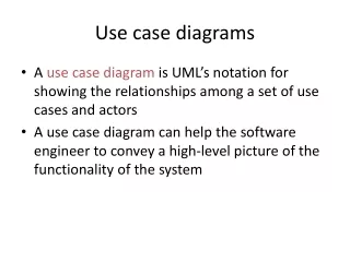
Use Case Diagrams Introduction and importance • Use cases are widely regarded as one of the important artifacts needed to successfully develop complex software systems • Use cases define the scope of the system and clarify the behavioral system requirements
Use Case DiagramsIntroduction and importance • Provide a basis for a coherent conceptual understanding of the system under consideration without requiring knowledge of software design or implementation technology • Used as organized means of capturing domain expertise
Use Case DiagramsIntroduction and importance • Can be used to track the progress of the system development effort • Provide means to trace requirements to the design • Provide the basis for developing system acceptance tests
Use Case Driven Analysis Req.ts Design Impl. Test Use Cases bind these workflows together
Use Cases Drive Iterations • Drive a number of development activities • Creation and validation of the system’s architecture • Definition of test cases and procedures • Planning of iterations • Creation of user documentation • Deployment of system • Synchronize the content of different models
Use Case DiagramsIntroduction and importance • The identification of use cases and actors occurs during the initial requirements analysis phase of a project • The use cases most essential to the system are selected, analyzed, and specified.
Use Case DiagramsIntroduction and importance • These essential use cases eventually become the basis for defining the architecture of the system during the first iterations of system development • The use cases are then allocated to iterative releases, which are planned and eventually executed
Use Case DiagramsIntroduction and importance • In the requirements phase of each delivery, the use cases allocated to that delivery are analyzed and completely specified • the use cases would then be realized by domain level analysis/design using class and interaction diagrams
Use Case DiagramsIntroduction and importance • The domain level realization is further refined into a detailed design that typically employs class and interaction diagrams and often includes state transition diagrams and/or decision tables.
Use Case Diagrams Use Case Diagram Rules • Use a “stick man” figure for an actor, and show the actor’s name below the stick man • The UML standard allows for the option of using a class rectangle with the stereotype «actor» Stereotype «actor» Sensor
Use Case Diagram Rules • The only valid relationship between an actor and another actor is generalization
Use Case Diagram Rules • Use only the following relationships between use cases • Use the include relationship to show that the behavior of one use case is wholly and unconditionally used in another use case • Use the generalizationrelationship to show that a use case is a specialization of another use case
Use Case Diagram Rules • the include relationship
Use Case Diagram Rules • the generalization relationship
Use Case Diagram Rules • Use the extend relationship to show that one use case conditionally augment (or extend) the behavior of another use case.
Use Case Diagram Rules • Extension points for a base use case are identified within the specification of that base use case • These are the locations where another use case may extend the base use case. These extension points are optionally shown in a diagram by listing them in a compartment of the base use case bubble under the heading “extension points • The extending relationship identifies, within parenthesis, the extension point(s) in the use case being extended
Identify, within brackets, the condition under which the extension is executed
Use Case Diagram Rules • There must be one extension point listed for each segment identified in the extension use case • Although considered optional, it is recommended that the extending relationship also identify, within brackets, the condition under which the extension is executed
Use Case Diagram RulesUse Case Packages • Use cases are often written and organized in layers of abstractions using Use Case Packages • A use case package contains a number of actors, use cases, their relationships, and perhaps other packages A Use Case Package
Use Case Diagramsand Packages Use the system Use case package
Examples of Use Case Diagrams Example 1: Medical Clinic Software Each use-case is described further by text document and by Scenarios developed using UML sequence diagrams
Example 3: Coffee Maker, “waiting state” is not a good name for a use-case (bad example)
Example 4: Automated Air Traffic Control System (AATCS)
Example 5: Use case diagram of the Internal Thermal Control subsystem
Requirements Elicitation Process • The process of requirements elicitation consists of the following steps • Identify Actors • Identify Scenarios • Identify Use Cases • Refine Use Cases • Identify Relationships between actors and Use Cases • Identify Initial Analysis Objects • Identify Non-functional requirements
Requirements Elicitation Process • Identifying Actors: Identify the users or external entities the system will interact with or support. Examples: Medical Clinic Software: Patient, Doctor, Scheduler, and the Clerk Actors may have a generalization relationship
Requirements Elicitation Process 2. Identify Scenarios of usage (user/actor stories): these are examples of typical user or actor interactions with the system. The are defined by a flow of events Example 1: Medical Clinic Software: in one scenario, the patient will contact the scheduler to make an appointment he finds an answer that office is closed, in another scenario he will contact the doctor to request medication, the doctor responds to him with the name of the medication
Requirements Elicitation Process 2. Identify Scenarios of usage (cont.) Example 3: The Coffee Maker waits for user input. There are six options to chose from: 1) add recipe, 2) delete a recipe, 3) edit a recipe, 4) add inventory, 5) check inventory, and 6) purchase beverage, the user chooses to delete a recipe which does not exist.
Requirements Elicitation Process 3. Identify Use Cases: Once scenarios of usage are identified, use cases are defined to model the main user-based functions of the system. Example: identify the “Make an Appointment” use case from one scenario and the “Request Medication” from another scenario
Requirements Elicitation Process • The process of requirements elicitation consists of the following steps • Identify Actors • Identify Scenarios • Identify Use Cases • Refine Use Cases • Identify Relationships between actors and Use Cases • Identify Initial Analysis Objects • Identify Non-functional requirements
Requirements Elicitation Process 4. Refine Use Cases: describe the details of each use case. A Textual template is used as well as UML interaction diagrams (UML sequence diagrams or object collaboration diagrams).
Requirements Elicitation Process 4. Refining Use Cases (cont.) An Example Sequence Diagram(to be discussed later)