Download
1 / 16
160 likes | 277 Views
Preliminary HV Results in Superfluid Helium. J. Long, J. Boissevain, J. Gomez, S. Lamoreaux, S. Penttila LANL. Review of HV system design. Superfluid LHe production. HV results. Amplification and large-gap E-fields. Neutron irradiation. Leakage currents.

E N D
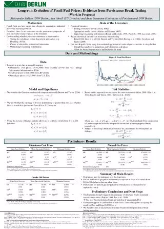
Preliminary HV Results in Superfluid Helium J. Long, J. Boissevain, J. Gomez, S. Lamoreaux, S. Penttila LANL Review of HV system design Superfluid LHe production HV results Amplification and large-gap E-fields Neutron irradiation Leakage currents Pressure dependence of breakdown (includes normal state) Noise issues Possible near future plans (pressurization)
Test System Design supply cryostat LHe reservoir LN2 reservoir vacuum chamber 77 K shield ~2 m air-vacuum HV feedthrough linear actuator LHe vessel G-10 foot Vacuum pump, T- sensor readout attachments
Superfluid Production in HV System 1. Fill HV system with normal state LHe at 4 K from full 500-liter supply dewar (1 hr) 2. Pre-cool LHe in both HV system and supply dewar (3 hrs) HV system: pump bath with roots blower (250 m3/hr) to 40 torr (2.2 K, above l-point) Supply: pump through vent with scroll pump (15 m3/hr) to ~ 230 torr (~3.2 K) 3. Restart LHe transfer, top off HV system with low pressure LHe above l-point (1hr) Leave roots blower on system Vapor P in HV system rises to ~ 90 torr (2.6 K) Transfer rate ~ 1 liter/min 4. Stop LHe transfer, leave roots blower on to pump system below l-point (3 hrs) Observe l-transition (rapid, complete cessation of all turbulence) at 35 torr (2.14 K) Process uses ~ 400 liters of LHe, takes 8 hrs Thanks to John Jarmer (LANSCE-6) for suggesting step 2
Amplification Measurement: Meter on Charger First attempted load cell on actuator: P = e0E2/2, Unrepeatable backgrounds at 4 K HVPS 50 kV CHC CHG CHF CCF CCC Q • Use SR570 current amplifier • Readout with ADC at 130 Hz
Readout SR570-A CURRENT PREAMP RG8 - BNC GAMMA 50 kV 1.25 mA HVPS TERMINAL STRIP 64 RG8 7m 500 pF NI-PCI 6024e ADC THOMSON DRIVE # CDM010i RS-232 OMNI- LINK PC LabVIEW 10 MW THOMSON MOTOR 360 W ~ 4500 N max GPIB LAKESHORE 218 16
HV-Charger Capacitance Close HV-G gap Monitor C with bridge on 100 kV feedthrough as increase Charger-HV separation Charger retracted to 5.0 cm where CHC = 1.1 ± 0.1 pF
Largest Potentials Attained 6/7/05 17:35, step G from 2.5 to 78 mm, initial V = 13 kV, P = 33.8 torr (T~2.13 K) = 258 nC Potential vs gap curve: VHG(7.8 cm) = (259 ± 34) kV Truncate sum at each point starting at t = 0 EHG(7.8 cm) = (33 ± 4) kV/cm Convert time axis to gap (.085 cm/s) (Design = 50 kV/cm…) Previous normal state results: CHC error 10% VHG = (570 ± 70) kV SR570 zero drift 3% EHG = (78 ± 9) kV/cm transients 2-13%
Largest Potentials Attained: V < 0 6/7/05 17:50, step G from 2.5 to 78 mm, initial V = -14 kV, P = 33.4 torr (T~2.13 K) = -268 nC Previous normal state results: VHG(7.8 cm) = (-269 ± 35) kV VHG = (-360 ± 60) kV EHG = (-49 ± 8) kV/cm EHG(7.8 cm) = (-35 ± 5) kV/cm
Radiation Effects • Results just shown (maximum potentials) actually attained with ~ 7 Ci n-source, • 50 cm from gap, nearly on-axis • Enhancement likely due to larger initial V at small gap (2.5 mm): • Slight improvement could have several sources (radiation, conditioning, switch to • negative polarity, more transients…) Maximum potential in absence of radiation: 6/7/05 17:23, initial V = 13 kV, P = 34.7 torr (T~2.14 K) VHG(7.8 cm) = (228 ± 30) kV
Leakage Current 6/7/05 22:12:39, return G to 3 mm gap P = 30 torr (T~2.09 K) 6/7/05 21:55:50, step G out to 8.0 cm initial V = -6 kV (!), P = 28 torr (T~2.06 K) QHC = 82.2 nC QHC = 88.6 nC (EHG = [-12 ± 1] kV/cm) CHG = 55 pF (bridge, ± 5%) _ iLEAK = (0.40 ± 0.45) nA CHC = (1.1 ± .1) pF DQHC = (6 ± 8) nC (3% zero shift) Previous normal state result: _ Dt = (1009 ± 30) s iLEAK = (-2 ± 20) pA
Leakage Current - Remarks • Would like to repeat with larger initial V and longer time delay • Attempts before data on last slide: attempt P (torr) initial V (kV) time delay final V (kV) 1 33 12.5 discharge (on pull-out) 2 32 12 (discharge) 0 3 32 -11.5 1 hr 1 hr 4 28 -11 0 5 25 11 (discharge) 6 25 10 (discharge) 7 26 -7 (discharge) 8 27 -7 (discharge) • Stability of HV in SF? Low P?
te) 75 75 Breakdown vs. Pressure, Temperature • l-point: pressure reading when SF transition observed in our system • data below l-point are highest attained in ~ 0.05 K bins above 2.05 K • Typical low-pressure normal state OR SF operation: 220 kV, 28 kV/cm at 8cm • Point at 890 torr (4.4 K) is system record: (638 ± 83) kV, (80 ± 10) kV/cm at 8 cm
Transients Normal State (322 torr) SF (34 torr) Inward trace SF (33 torr) + neutron rad SF (34 torr) V = 298 kV (13% increase) • Greater effect at low pressure • Enhanced by neutron radiation • ~ 20 ms rise time, ~100 ms FWHM, ~150 ms decay time, ~1-2 nC • Predominantly positive (negative) when HV positive (negative) • He gas bubbles? • Kerr Effect: E-field measurement less susceptible to this effect?
. DQ/Q = 3.2 hr (assumes old 2.7 W load) Pressurization Estimates Volume change for DP = 1 atm: DV = b V0DP = 2.6 l b = compressibility SF LHe = 10-7 Pa-1 (Keller, 3He and 4He) Have 2 spare bellows with DV = 1.4 l each (if initially stretched) Force on actuator: F = PA = 14 psi X 14 si + typical bellows resistance = 300 lb Actuators in used rated for 1000 lb Isothermal? P dV = McDT = 130 J DT = 10 mK Time system spends below 2 K: Need valve in neck above stainless can: Open/close while immersed in SF LHe 1” diameter minimum Leak rate: (1.1 atm – 0.9 atm)/ 3.2 hr X 2.6 l/atm = 160 cc/hr