Download
1 / 60
600 likes | 694 Views
This captivating image showcases the celestial sphere at a radio frequency of 408 MHz in a Hammer–Aitoff projection, dominated by the synchrotron radiation of relativistic electrons gyrating in the interstellar magnetic field. It reveals loops and filaments of radio emission extending beyond the Galaxy's plane. Uncover the fascinating cosmic phenomena associated with radio emissions, synchrotron radiation from spiraling electrons, and the role of relativistic plasma and magnetic fields in galactic processes. Explore X-ray sources and understand the significance of active galactic nuclei, supernova remnants, and other astronomical objects detected in the X-ray energy band. Dive into the intricate details of celestial radio and X-ray astronomy to unravel the mysteries of our universe.

E N D
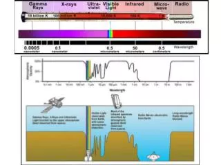
Images of the celestial sphere at a radio frequency of 408 MHz in a Hammer–Aitoff projection. This image is dominated by the radio emission of relativistic electrons gyrating in the interstellar magnetic field, the process known as synchrotron radiation. The radiation is most intense in the plane of the Galaxy but it can be seen that there are extensive ‘loops’ and filaments of radio emission extending far out of the plane. (Courtesy of Max-Planck-Institut fu ̈r Radioastrotiomie, Bonn.) 1 eV = 11600 °K -Emissioni associate direttamente ai fenomeni osservati nella banda ottica -Emissione radiazione di sincrotrone da parte di elettroni che spiralizzano in H. -Molte galassie emettono nel radio. radiazione non proviene dalla galassia stessa ma da giganteschi radiolobi che si estendono ben al dei confini. Queste energia viene fornita dal nucleo attivo della Galassia dalla quale viene espulsa nella forma di getti di plasma relativistico dando luogo a una sorgente estesa. -Importante e nuova componente: Plasma relativistico e campi magnetici. I raggi cosmici sono una componente del plasma relativistico presente nella nostra galassia. -I resti di supernovae sono sorgenti radio: sorgenti di radiazione di sincrotrone, capaci di accelerare particelle cariche. -impulsi radio da stelle di neutroni magnetizzate, rotanti, compatte densita’ 1018 Kg/m3≥≥
In questa regione sotto al mm forte assorbimento in atm. Dovto a vapore acqueo, CO2 e altre molecole. Fra 350-850 mm bisogna operare in atm secca e/o alta quota Hawaii 4200m. JCMT, CSO, SMA. Chile 5100m. ALMA Polo Sud. In altre parti di spettro Fuori atm con satelliti… 1 mm. In questa regione i rivelatori usati sono ricevitori eterodina e bolometri. -Domina in questa regione CMB osservata a 5,7 mm. -emissione molecole gas interstellare: H non osservato 0 dipolo elettrico, CO. + diffusa emissione di sincrotrone del mezzo interstellare CO CMB
UHURU (1970-1973) -survey of X-ray sources in the 2-20 keV -5 × 10⁻⁴ the flux from the Crab Nebula -resolution of about 30 arc minutes. -two sets of proportional counter, each with ~0.084 m2 -Pulse-shape discrimination -anticoincidence techniques to reduce the background due to particles -Pulse-height analysis -0.52° X 0.52° and 5.2° X 5.2° -0.52° detector gave finer angular resolution. -5.2° detector had higher sensitivity for isolated sources. X-ray catalog, contains 339 objects and covers the whole sky in the 2—6 keV band. The UHURU map of the brightest X-ray sources in the 2–6 keV energy band. The identifications of a number of the brightest sources are indicated (Forman et al., 1978). These include the quasar 3C 273, the Coma, Perseus and Virgo Clusters of galaxies, the radio galaxy Cygnus A, the low mass X-ray binary Sco X-1, the high mass binaries Cyg X-1 and Cyg X-3 and the supernova remnant the Crab Nebula. the distribution of sources consists of a Galactic population of the types shown in Fig. 1.13a as well as an isotropic distribution of extragalactic sources, most of them being associated with active galactic nuclei
The variability of some of the Galactic sources was found to be due to the fact that the compact X-ray emitter is a member of an eclipsing binary star system. In a number of these cases, the X-ray binaries were found to contain ‘pulsating’ X-ray sources and these were soon identified with magnetised rotating neutron stars but, in the cases of the X-ray sources, the source of energy is the infall of matter transferred from the primary star, the process known as accretion. in a number of cases, the masses of the invisible secondaries exceed the upper limit for stable neutron stars. These objects must be associated with stellar-mass black holes in binary systems and as such are objects of the greatest astrophysical interest. In extragalactic astronomy, the nuclei of active galaxies were found to be intense and often variable X-ray sources, the emission processes taking place close to the Schwarzschild radius of a supermassive black hole. Other important classes of extragalactic X-ray sources are the clusters of galaxies. In 1978, the Einstein X-ray Observatory was launched. It provided the first high resolution images of many X-ray sources and made deep surveys of small areas of sky. Many different classes of astronomical object were detected as X-ray sources including regions of star formation and normal galaxies. Perhaps most significant of all was the fact that X-ray emission was detected from all types of star and not just from the binary sources in which there are special reasons why they should be strong X-ray sources.
Atmosfera opaca ai raggi X a causa dell’assorbimento per effetto fotoelettrico negli strati di atmosfera: quindi esperimenti su satellite. Rivelatori usati: contatori proporzionali, scintillatori, contatori a microcanali e CCD. Questi ultimi hanno una eccellente risoluzione spaziale e di carica, usati nelle moderne missioni X. Calorimetri/bolometri, convertono l’energia dell’X in calore con ottima risoluzione. Vanno tenuti a bassa temperatura. Fino a 20keV contatori proporzionali, contatori a scintillazione fino a 1MeV. Tipico Detector per Raggi X: -Contatori di anticoincidenza: il rivelatore e’ coperto da uno strato di scintillatore plastico o liquido con funzione di anticoincidenza per rigettare i raggi cosmici. -Ricostruzione della forma del segnale. L’X da un segnale stretto e rapido dovuto a ionizzazione locale della conversione dell’X a fine range. Una particella cosmica perde energia lungo il cammino in modo distribuito e da un segnale piu’ largo. -Strati alternati di cristalli scintillatori sensibili ai fotoni : Scintillatori e scintillatori plastici insensibili ai fotoni.I fotoni daranno segnale nel cristallo e non nel plastico. Le particelle cariche in entrambi i rivelatori. -collimatori. Efficaci a piccoli angoli di incidenza che accuratamente riproducono l’immagine del cielo nel piano focale. Per raccoglier molti fotoni occorrono molti collimatori quasi paralleli uno all’interno dell’altro convergenti nel piano focale.
The AXAF-I mission willdevelopeand place into orbit a telescope for capturing high-resolution images and spectra of X-ray sources. Its imaging observations will produce "picture-like" images analogous to those made in visible light with an optical telescope. It uses optics and detectors which are sensitive to X-rays to capture images of astronomicalphenomenacharacterized by very high temperatures. Reticoli diffrazione Bragg (0,1-9 keV), CCD (0,1-10 keV) ,Microchannel plate (0,1-10 keV).
In an X-ray telescope, the mirrors are muchdifferent from those in optical telescopes. With theirvery short wavelengths, X-rays are notreflected from the surface of a conventionalmirror. X-ray telescopesuse "grazing-incidence" mirrorsfinelypolishedcylinders of glass Thisconfiguration, coupled with a slight curvature of the surfaces, funnels the raystoward a point of focus behind the mirrors. four sets of thesecylindricalmirrors, mountedconcentrically in a nested array in order to increase the area for collecting X-ray energy. The diameter of the largestmirror set will be 47.2 inches (1.2 m). Piccola componente campo elettrico perpendicolare alla superficie. Incidenza radente.
The sensor of the imaging detector consists of a two-stage configuration (chevron) of 100 mm x 100 mm Galileo Electro-Optics Corp. radioisotope-free leadoxideglassmicrochannelplates (MCPs). A UV/Ionshieldconsisting of aluminizedpolyimidepreventslowenergyions, lowenergyelectrons.The front MCP iscoated with CsIin order to increase the quantum efficiency over that of the bare glass of the MCP. An incident x-ray photoninteractswithin a channel (pore) of the front MCP producingone more electrons with a probabiltythatdepends on the photonenergy. The initial electron or electrons are accelerated by an appliedelectricfieldacross the plates and generate secondary electrons;thisprocessultimatelyproduces and EUV and UV radiation from reaching the sensorsurface. The UV/Ion shieldisheldelectrically positive (+100 Volts) with respect to the front surface of the MCP in order to preventelectronsgenerated in the shield. The primarycomponents of the (HRC) are two Micro-Channel Plates (MCP). Theyeachconsist of a 10-cm squarecluster of 69 milliontinylead-oxideglasstubesthat are about 10 micrometers in diameter (1/8 the thicknessand 1.2 millimeterslong. The tubeshave a special coatingthatcauseselectrons to be releasedwhen the tubes are struck by X-rays. (-) The axes of the millions of tubesthatcomprise the input and output MCPs are notparallel to the opticalaxisbut are canted ("biased") at an angle of 6°
The electronicreadoutsystemis a crossedgridcharge detector (CGCD). The CGCD consists of twoplanes of wires (one set of wiresorthogonal to the other) mounted on a laser ruledceramicsubstrate. The wires (100 microns in diameterwith 200 micron center to center spacing) are resistivelycoupled (40 kOhm); everyeighthwireisconnected to a charge sensitive preamplifier. The cloud of electronsemerging from the rear MCP iscollected by severalwires. 65 preamplifiers per wireplane (axis) divide the image plane into 64 x 64 coarse positions. The fine position (digitized to 6.429 microns) isdetermined from a "threetap" centroidcalculation. The combined MCP/CGCD iscapable of < 25 micron (FWHM) resolution over the entirefield of the detector. TEST HCR
(cm2) , m= s (cm2) x N (nuclei/cm3) m x t (probabilita’ di inetrazione in t) • N (nuclei/cm3) = NAv/grammo-atomo x gr/cm3 NAv=6.10^23 atomi/grammo-atomo
trasferimento fra 2 pixel
The Chandra Advanced CCD Imaging Spectrometer(ACIS) isone of two focalplaneinstruments. Thisinstrumentis an array of chargedcoupleddevices (CCD's) Thisinstrumentisespeciallyusefulbecauseit can make X-ray images, and at the same time, measure the energy of eachincoming X-ray. Itis the instrument of choice for studying temperature variationsacross X-raysourcessuchasvastclouds of hot gas in intergalacticspace, or chemicalvariationsacrosscloudsleft by supernova explosions. consiste in un circuito integrato formato da una riga, una griglia, di elementi semiconduttori in grado di accumulare una carica elettrica proporzionale all'intensità della radiazione X che li colpisce. Questi elementi sono accoppiati in modo che ognunodi essi, sollecitato da un impulso elettrico, possa trasferire la propria carica ad un altro elemento adiacente. Inviando al dispositivo (device) una sequenza temporizzata d'impulsi, si ottiene in uscita un segnale elettrico grazie al quale è possibile ricostruire la matrice dei pixel che compongono l'immagine proiettata sulla superficie del CCD stesso.
BEPPO-SAX 1996-2003 Energy Range : 0.1 - 300 keV
MECS (Medium Energy Concentrator Spectrometers): a medium energy (1.3-10 keV) set of three identical grazing incidence telescopes with double cone geometry with position sensitive gas scintillation proportional counters in their focal planes. LECS (Low Energy Concentrator Spectrometer): a low energy (0.1-10 keV) telescope, identical to the other three, but with a thin window position sensitive gas scintillation proportional counter in its focal plane. HPGSPC, a collimated High Pressure Gas Scintillation Proportional Counter (4-120 keV) PDS, a collimated Phoswich Detector System (15-300 keV). Perpendicular to the axis of the NFI and pointed in opposite directions there are two coded mask proportional counters (Wide Field Cameras) that provide access to large regions of the sky in the range 2-30 keV. Each WFC has a field of view of 20° x 20°(FWHM) with a resolution of 5'. Finally, the four lateral active shields of the PDS will be used as a monitor of gamma-ray bursts with a fluence greater than about 10-6 erg cm-2s-1 in the range 60-600 keV, with a temporal resolution of about 1 ms.
LECS: The Detector Unit (DU) consists of a gas cell, a photomultiplier tube (PMT), Front End Electronics (FEE) and two high-voltage supplies. The detector is protected by an Al cover on which a shutter mechanism is mounted. The shutter will be opened once in orbit. A uniform electric field between the entrance window kept at -20 kV is proportional to the energy of the incident X-ray but, unlike a conventional GSPC, also depends on the depth at which the X-ray photon was absorbed. This depth is determined by measuring the duration of the scintillation light and is referred to as the ``Burstlength''. Thus an X-ray absorbed deep within the gas cell will have a shorter burstlength than one absorbed directly below the entrance window. Gas XENON
An X-ray photon absorbed in the gas cell liberates a cloud of electrons. A uniform electrical field across the cell drifts the cloud up to the scintillation region, with an higher electric field, where UV light is produced through the interaction of the accelerated electrons with the Xe ions. The amplitude of the UV signal, detected by a PMT, is proportional to the energy of the incident X-ray. The UV readout system consists of a crossed-wire anode position sensitive Hamamatsu photomultiplier (PMT) with quantum efficiency of ~20%. XENON GSPC gas scintillation proportional counter
The HPGSPC instrumentis a High Pressure (5 atm.)(Gas ScintillationProportionalCounterfilled with a high purity gas mixture of Xenon (90%) and Helium (10%) at5 atmospheres. Afterpenetrating the berylliumwindow, the X-rayphotonisabsorbed in the gas cell by a Xenonatom via the photoelectriceffect. The primaryphotoelectronemittedgives rise to a localisedcloud of secondaryelectronsat the position of X-rayabsorption. The secondary electron cloud, driven by a relatively moderate electricfield, afterdrifting in the so calledDriftRegion, enters a high fieldregion(ScintillationRegion) in which the electronsacquiresufficientenergyto excite the Xenonatoms. As a result of collisions, the excitedatomsformexciteddiatomicXenonmoleculeswhichthendeexcite by the emission of VUV photonsin the 1500-1950 angstrom range. Typicalduration of scintillation, measuredas the time intervalbetween the 10% and 90% of the signal, is 3.5 -6sec and doesnotdepend on the energy. In the case of the HPGSPC VUV light iscollected by an array of sevenphotomultipliersin an Anger Camera configuration. The number of electronsemitted per keV by the cathode of centralphotomultiplierisabout 250. 5 atmosfere BEPPO-SAX a High Pressure Gas Scintillation ProportionalCounter (HPGSPC) operatingin the 3-120 keVenergy band
The hard X-rayenergyband (15-300 keV) covered by the PDS experimentisnowassumingkeyimportance for high energyastrophysicsthanks to manyexciting and unexpectedresultsobtained with gamma-rayastronomy experimentslike BATSE and OSSE aboard CGRO, SIGMA aboard the GRANAT satellite and balloon experiments. In addition to wellknownclasses of strong hard X-rayemitters (galactic X-raypulsars, blackholecandidates, AGN) The detectionplane of PDS is an array of fourscintillation detectors. Each of the four detectors iscomposed by twocrystals of NaI(Tl) and CsI(Na) opticallycoupled and formingwhatisknownas PHOSWICH (acronym of PHOsphorsandWICH). The NaI(Tl) thicknessis 3 mm and the CsI(Na) thicknessis 50 mm. The scintillation light produced in eachphoswich (PHW) isviewed, through a quartz light guide, by a PMT EMI D-611. The NaI(Tl) actsas the X-ray detector, while the CsI(Na) scintillatoractsas an activeshield. The scintillationevents (due to photons or chargedparticles) detected by eachphoswich can be dividedintothreeclasses: thosethatdepositenergyonly in the NaIcrystal (NaIevents or ``goodevents''); thosethatdepositenergyonly in the CsIcrystal (CsIevents); thosethatdepositenergy in bothcrystals(mixedevents). The events of the first class are accepted, while the events of the othertwoclasses are rejected. BEPPO-SAX