Download
1 / 105
1.09k likes | 1.33k Views
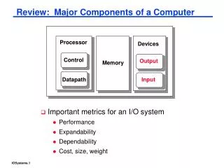
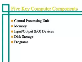
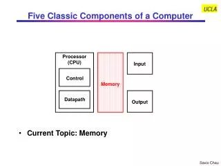
. Control. Control. Datapath. Datapath. Five Classic Components of a Computer. Current Topic: Input and Output. Network. Processor. Processor. Input. Input. Memory. Memory. Output. Output. Peripheral Devices. . What You Will Learn in This Set of Lectures. I/O System Overview

E N D
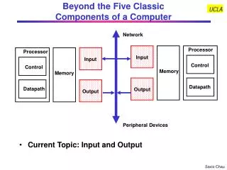
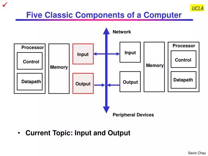
Control Control Datapath Datapath Five Classic Components of a Computer • Current Topic: Input and Output Network Processor Processor Input Input Memory Memory Output Output Peripheral Devices
What You Will Learn in This Set of Lectures • I/O System Overview • I/O System Design Considerations • I/O System Design Parameters • Connectivtiy • Protocol • Access Control • Performance • Expandability • Failure Handling • Operating System Support • I/O Implementation Example
Who Cares About I/O? • CPU Performance: 60% per year • I/O system performance limited by mechanical delays (disk I/O) < 10% per year (IO per sec or MB per sec) • Amdahl's Law: system speed-up limited by the slowest part! 10% IO & 10x CPU 5x Performance(lose 50%) 10% IO & 100x CPU 10x Performance (lose 90%) • I/O bottleneck: Diminishing fraction of time in CPU Diminishing value of faster CPUs
I/O System Architecture Overview User Application system call System Interface Software Operating System Device Driver Device Driver Protocol can be defined at all levels Memory or I/O Bus Logical I/O Controller I/O Controller Hardware Media Physical I/O Device I/O Device
How is the I/O System Related to Processor 1 Branch Target Address 0 ExtOp ALUSrc ALUOp RegDst MemWr Branch MemtoReg RegWr Control Signals Control Signals Control Signals Main Control 4 PC+4 PC+4 Adder Imm16 Imm16 BusA Exec Unit Rs BusB Ra A Zero PC Rt Rb Do IF/ID Register ID/EX Register EX/Mem Register Mem/Wr Register RA RFile 1 WA Rw Wr Di Rt Di 0 0 Rd I 1 I/O Controller I/O Device Memory Hierarchy
A Classificaiton of I/O According to the Targets of I/O Operation • Processor to Memory Very low latency, very high throughput, very low protocol overhead • Processor to Peripheral Latency, throughput, and protocol overhead vary according to the I/O devices • Processor to Processors • Tightly Coupled: all processors share a physical memory Low latency, high throughput, low overhead protocol, coherence problem • Loosely Coupled: each processor has its own physical memory Medium latency, medium throughput, high protocol overhead, scalable • Processor to Network High latency, low throughput, high protocol overhead, very scalable
I/O System Example Processor Processor Main Memory Cache Cache Memory - I/O Bus Network Interface Controller IEEE 1394 Bus Interface Contorller I/O Controller I/O Controller Disk Disk Graphics Network To Other Processors or Peripherals on the IEEE 1394 Bus
I/O Devices Examples Device Behavior Partner Data Rate (KB/sec) Keyboard Input Human 0.01 Mouse Input Human 0.02 Line Printer Output Human 1.00 Floppy disk Storage Machine 50.00 Laser Printer Output Human 100.00 Optical Disk Storage Machine 500.00 Magnetic Disk Storage Machine 5,000.00 Network-LAN Input/Output Machine 20 – 1,000.00 Graphics Display Output Human 30,000.00 • See Backup Slides for More Detailed Information about Some of the I/O Devices
Device A? Device B? Device C? Device B? Device D? Bus A? Bus C? Bus B? Device A Device B ? ? Bus B ? ? ? Device C Device B Device D I/O System Design Process • Establish Requirements: Understanding What You Need • Select the I/O System That Has the Required Capability: Understand What the I/O System being Considered Can Do • Integration: Understand How Everything Fits Together • Implementation
Star Tracker Inertia Measurement Unit Power Control Unit Star Tracker Telecom Subsystem Inertia Measurement Unit Power Control Unit Telecom Subsystem I/O System Design Example: Establish Requirements • Design an I/O architecture for a spacecraft that has the following equipment Data Rate: 8 Mbps 1000 samples/sec Latency < 0.1 ms Data Rate: 5 Kbps 1transaction/sec Latency < 10 ms Data Rate: 10 Kbps 1000 samples/sec Latency < 0.1 ms Data Rate: 400 bps 2 commands/sec Latency < 0.5 sec Flight Computer (CDH) Flight Computer (ACS) Flight Computer (Payload) I/O? Thruster Control Unit Wide Angle Camera High Resolution Camera Radar Sounder Altimeter Thruster Control Unit Data Rate < 100 bps 10 commands/sec Latency < 0.1 ms Data Rate: 20 Mbps 2 frames/sec Latency < 0.5 sec Data Rate: 20 Mbps 2 frames/sec Latency < 0.5 sec Data Rate: 1 Mbps 1 transaction/sec Latency < 1 sec Data Rate: 5 Kbps 100 samples/sec Latency < 0.01 sec • System Constraints (Prioritized): • Total power consumption of the avionics system < 100 W. • The I/O system power consumption should be less than 35% of the avionics system. • Each subsystem has to meet the latency and throughput requirements • System reliability should exceed 12 years (i.e., requires fault tolerance) • The system design should be scalable and distributed. • Maximum distance between subsystems is 5 meters. Average distance is 3 m. • Minimize the cable mass.
Metrics IEEE 1394 (Cable version) IEEE 1393 Fiber Channel I2C UART (Direct Interface) Ethernet (IEEE 802.3) Raw Bandwidth 100, 200, 400 Mbps 200 to 1000 Mbps 1 Gbps 100, 400 Kbps 115 Kbps to 10 Mbps 10, 100 Mbps Latency 125 ms max 196 bits N nodes 196 bits N (loop) Undeterministic < 100 ns Undeterministic Topology Tree Ring Loop, Star, Switch network Multi-Drop Star Multi-Drop Signal Level Protocol Async Async Async Async Async Async Cable Type Electrical (Twisted pair) Optical Fiber Optical Fiber, Electrical (Twisted pair) Electrical (Single end) Electrical (Twisted pair) Electrical (Coaxial) Power Note 1 1 W/node 8 W/node 8 W/node 5 mW/node 35 mW/node 150 mW/node Multi-master Yes Yes Yes Yes No Yes Max. # Nodes 64 127 127 for Loop 128 N/A 248 Max Bus Length Note 1 72 m (4.5 m/hop) 10 km, (100m/hop) Fiber: 10 km Electrical: 30m Approx. 40 m (load<400 pf) Approx. 10 m 500 m Protocol Overhead 8 % for 278 byte data 3 bytes per 53-byte frame 25 % for 2168 byte data Note 2 1 byte address +Ack bit / byte 1 start + 1 stop bits/byte (25%) 64 bytes / msg (msg < 1500 B) I/O System Design Example: Candidate I/O Interface
I/O System Design Example: Selecting an I/O Interface • There are 17 nodes in the system and the power allocation of the I/O system is 35 W. This eliminates the Fiber Channel and the IEEE 1393 • The latency requirement eliminates the I2C and Ethernet • The total bandwidth requirement of the system 56 Mbps. This eliminates the UART • The system reliability requirement eliminates the IEEE 1394 bus because tree topology is not very fault tolerant • All interface options, except the UART, are buses and thus meet the scalability requirement. All bus options here support distributed processing. • The distance requirement prohibits the search for a parallel bus • All interface options, except the UART, are serial buses and thus meet the cable mass requirement PROBLEM: WE DON’T HAVE AN OPTION THAT CAN MEET ALL REQUIREMENTS! Resolution: Since power consumption and latency are technology dependent and difficult to improve, the next best option is to improve system reliability using fault tolerance design techniques. Therefore, the IEEE 1394 is the best choice in this case but need to be enhanced with fault tolerance design techniques. Use dual redundant buses. Check: Since redundant buses have to be used, the number of interfaces of the IEEE 1394 bus is doubled. The power consumption will be 17 x 1 W x 2 = 34 W. This is OK since it is still within the 35 W power constraint.
Establish Requirements: Understanding What You Need • Application and Environments of the I/O System • Home Computing • Industrial Control • Network • Aerospace • Capability Required • Number of I/O Devices • Data Rate of the I/O Devices • Required Throughput: How much data need to be transferred? • Maximum Latency: How much delay the I/O devices can tolerate? • Future Expansion • Constraints • Cost Constraints: How much money do you have? • Power Constraints: Do you have enough power? • Electrical Interface Constraints Imposed by the I/O devices • Mechanical Interface Constraints Imposed by the I/O devices • Logical Interface Constraints: Protocol Imposed by the I/O devices
Select I/O System with Required Capability: Understand the I/O System Being Considered • Performance: How much data can be handled by I/O system being considered • Throughput: function of Bit Rate, Bus Width, Block Size, Protocol Overhead • Latency or Response Time • Impact on Processor Performance • Expandability: How many devices can it handle • Bus Length: Parallel Buses Are Shorter, Serial Buses Are Longer • Drive Capability: Bus Loading, Transmission Line Effect • Multi-Level Buses: Bridge Between Buses • Access Control: How to arbitrate I/O requests among nodes • Master-Slave: One Master Controls All Transactions • Passive Slaves, Active Slaves (interrupt) • Multi-Master: Arbitration Required Among Masters (processors, controllers) • Failure Handling: What the I/O system can do in case of failures? • Reliability vs. Availability • Fault Tolerant: Fault Detection, Fault Isolation, Fault Recovery
Integration: Understand How Everything Fits Together • Physical Interface with the I/O Devices • Electrical Interface • Mechanical Interface • Topology • Star, Multi-Drop, Ring, Tree, etc. • Protocol: Rules of Communication with the I/O Devices • Signal Level Protocol • Synchronization: Synchronous (Clocked), Asynchronous (handshake) • Packet / Message Level Protocol • Addressing Capability:Directed, Broadcast, Multi-Cast • Transaction Types: Split, Unified • Operating System Support • Software Device Driver • Method of Addressing the Devices: I/O Address, Memory Mapped I/O: • Processor & I/O Devices Interaction: Interrupt, Polling, DMA, I/O Processor • Resource Management: Sharing of I/O Devices • Protection: Ensure No Conflicts among I/O Devices
Implementation • If Your I/O System Requirement Can be Met by Standard Interfaces • It is easy! Just purchase commercial off-the-shelf (COTS) components, software, and test equipment and then integrate them • If Your I/O System Requirement Needs Custom Design, You Have to • Specify the protocol and timing of the signals at the interface • Design the logic required to implement the specification • Realize the logic design in hardware • Write the software driver to drive the hardware
Key I/O Design Parameters to be Discussed • Connectivity • Protocol • Access Control • Performance • Expandability • Failure Handling • Operating System Support Typical I/O System Layers and Key Parameters • System Interface • Operating System Support • Failure Handling • Logical • Protocol • Failure Handling • Physical • Protocol • Connectivity • Access Control • Performance • Expandability • Failure Handling
Input Input Memory Output Output Connecting I/O to Processor: Direct Interface • Ad Hoc • No definite number of signals, protocol, electrical interface etc. • Standards • RS232: Serial interface. Signals include Request-to-Send, Clear-to-Send, TxData, RxData • UART (Universal Asynchronous Receiver Transmitter): Serial interface protocol, usually used with the RS232 • IEEE 1284: Parallel interface, commonly used for printer port on PCs Processor Control Datapath
Input Input Output Output Connecting I/O to Processor: Buses • A Bus is • shared communication link • single set of wires used to connect multiple subsystems • Bus is also a fundamental tool for composing large, complex systems • systematic means of abstraction Processor Control Memory Datapath
Types of Buses • Processor-Memory Bus (design specific) • Used for Process-to-Memory I/O • Usually is parallel, short, high speed and on the processor broad • Match the processor and memory interfaces to maximize bandwidth • Optimized for cache block transfers • I/O Bus (industry standard) • Used for Process-to-Peripheral, loosely coupled Processor-to-Processor, and Processor-to-Network I/Os • Usually is serial, lengthy, slower, and implemented by cables but flexible • Need to match a wide range of I/O devices • Connects to the processor-memory bus or backplane bus through bridges • Backplane Bus (standard or proprietary) • Used for Process-to-Peripheral, tightly coupled Processor-to-Processor I/Os, and Processor-to-Network I/Os • Backplane: an interconnection structure within the chassis • Allow processors, memory, and I/O devices to coexist • Usually is parallel, speed is between Processor and I/O Bus • Cost advantage: one bus for all components • See Backup Slides for Bus Surveys
A Computer System with One Bus: Backplane Bus • A single bus (the backplane bus) is used for: • Processor to memory communication • Communication between I/O devices and memory • Advantages: Simple and low cost • Disadvantages: slow and the bus can become a major bottleneck • Example: IBM PC - AT
A Two-Level Bus System • I/O buses tap into the processor-memory bus via bus adaptors: • Processor-memory bus: mainly for processor-memory traffic • I/O buses: provide expansion slots for I/O devices • Examples: • Apple Macintosh-II • NuBus: Processor, memory, and a few selected I/O devices • SCCI Bus: the rest of the I/O devices
A Three-Level Bus System • A small number of backplane buses tap into the processor-memory bus • Processor-memory bus is used for processor memory traffic • I/O buses are connected to the backplane bus • Advantage: loading on the processor bus is greatly reduced • Example: See PCI Bus Example
The General Organization of a Bus • Data Lines Carry Information Between the Source and the Destination: • Data and Addresses • Complex Commands • Control Lines: • Signal Requests and Acknowledgments Control Lines Data Lines
Typical Bus Operation and Interface Control • I/O Operation Consists of • Check if Device is Available (e.g., check busy signal) • Send Operation Parameters (e.g., send read/write signals, address) • Data Transfer (e.g., read or write to Data, Control, Status registers) • Termination (e.g., send or receive acknowledge signal) • Methods are: • Programmed I/O • Interrupt- Driven • Direct Memory Access (DMA)
How to Specify a Bus
Device 1 Device 2 Device N Short protection resistors Data Isolation (transformer, Optical etc.) Command / Address Termination Resistors Bus couplers Device Device Device Device Device Device Device Device Device Device Examples of Bus Topologies • Multi-Drop Bus • One media is shared by many devices • If the media is a cable, each device needs a coupler to “tap” into the bus • Need to consider short protection, electrical isolation, and termination • Point-to-Point Buses • One media between each pair of devices • Many topologies are possible (e.g., ring, tree, star etc.) • Short protection, electrical isolation, and termination are less critical Ring (e.g. Token Ring) Tree (e.g. IEEE 1394) Star (e.g. Fiber Channel) Device Device Device Device
R/W Address (Requesting Node) Rd Addr 1 Rd Addr 2 Data (Responding Node) Data1 Data2 Examples of Bus Transaction Types • Unified Transaction • Request (address and read/write commands) is followed immediately by response (data) • Split Transaction • Request is not followed immediately by response. Other requests can be issued in-between R/W Address (Requesting Node) Rd Addr 1 Rd Addr 2 Data (Responding Node) Data1 Data2
Examples of Bus Protocols • Synchronous Bus: • Includes a clock in the control lines • A fixed protocol for communication that is relative to the clock • Advantage: involves very little logic and can run very fast • Disadvantages: • Every device on the bus must run at the same clock rate • To avoid clock skew, they cannot be long if they are fast • Asynchronous Bus: • It is not clocked • It can accommodate a wide range of devices (fast and slow) • It can be lengthened without worrying about clock skew • It requires a handshaking protocol which can significantly reduce the effactive bandwidth • Some more details in the Protocol discussion
Backplane Bus Example: PCI Cache Memory More details in the Protocol discussion
Key Features of PCI Bus • 32-bit or 64-bit bus running at 33 MHz or 66 MHz, synchronized to host processor clock • Block oriented data transfer • Reconfigure bus nodes upon system startup or configuration changes (Plug-and-Play) • Multi-master, but only one master has bus arbitration capability • Sub-buses include • Address and Data Bus (Multiplexed) • Command and Byte Enable Bus • Interface Control Signals • Arbitration Signals • Error Signals • Reflected wave signal switching • Device select and negative acknowlegment • More details in the Protocol discussion
Serial Bus Example: IEEE 1394 (Firewire) More details in the Protocol discussion CPU memory I/O CPU nodes Any Backplane Bus IEEE 1394 Bus (backplane environment) bridge ports IEEE 1394 Bus (Cable environment) CPU memory I/O CPU I/O I/O I/O Any Backplane Bus IEEE 1394 Bus (backplane environment) bridge nodes Note: IEEE 1394 Bus is a serial bus in both backplane and cable environments
Key Features of the IEEE 1394 Bus • A digital interface – there is no need to convert digital data into analog and tolerate a loss of data integrity • Physically small - the thin serial cable can replace larger and more expensive interfaces • Adopts a tree topology in cable environment and multi-drop topology in backplane enviroment • Easy to use - no need for terminators, device IDs, or elaborate setup • Hot pluggable - users can add or remove 1394 devices with the bus active • Inexpensive - priced for consumer products • Scalable architecture - may mix 100, 200, and 400 Mbps devices on a bus • Flexible topology - support of daisy chaining and branching for true peer-to-peer communication • Fast - even multimedia data can be guaranteed its bandwidth for just-in-time delivery • Non-proprietary • Mixed asynchronous and isochornous traffic • More details in the Protocol discussion
Advantages of Buses • Versatility: • New devices can be added easily • Peripherals can be moved between computer systems that use the same bus standard • Low Cost: • A single set of wires is shared in multiple ways • Easy to maintain • Manage complexity by partitioning the design
Disadvantage of Buses • It creates a communication bottleneck • The bandwidth of that bus can limit the maximum I/O throughput • The maximum bus speed is largely limited by: • The length of the bus • The number of devices on the bus • The need to support a range of devices with: • Widely varying latencies • Widely varying data transfer rates • A single point of failure: one bus failure (e.g., short to ground) can fail the entire system
Signal Level Protocol:Typical Synchronous Protocol • Wait signal is optional: Slave can use this signal to indicate when it is prepared for data transfer • Actual transfer goes at bus rate Clock (master) Valid (master) R/W Address (master) Cmd+Addr Wait (slave) Data (master/slave) Data1 Data1 Data2
Signal Level Protocol: Typical Asynchronous Protocol (Handshaking) Write Transaction • t0 : Master has obtained control and asserts address, direction, data Waits a specified amount of time for slaves to decode target • t1: Master asserts request line • t2: Slave asserts ack, indicating data received • t3: Master releases req • t4: Slave releases ack Address Data Rd / Wr (Master) Req (Master) Ack (Slave) Master Asserts Address Next Address Master Asserts Data t0 t1 t2 t3 t4 t5
Signal Level Protocol: Typical Asynchronous Protocol (Handshaking) Read Transaction • t0 : Master has obtained control and asserts address and direction. Waits a specified amount of time for slaves to decode target • t1: Master asserts request line • t2: Slave asserts ack, indicating ready to transmit data • t3: Master releases req, data received • t4: Slave releases ack Address Data (Slave) Rd / Wr (Master) Req (Master) Ack (Slave) Master Asserts Address Next Address t0 t1 t2 t3 t4
Asynchronous Protocol for Multiplexed Bus • Three Control Lines • ReadReq: Indicates a Read Request for Memory • Address is Put on the Data Lines at the Same Time • DataRdy: Indicates the Data Word is Now Ready on the Data Lines • Data is put on the Data Lines at the Same Time • Ack: Acknowledge the ReadReq or the DataRdy of the Other Party Read Example (master) (master) (slave) (master/slave) (master) (slave) (slave/master) (slave)
Address Phase Done State Diagram for Asynchronous Multiplexed Bus Data Phase Done I/O Devices (master) DataRdy Ack DataRdy Put Address on data lines; Assert ReadReq 5 Read memory data from data lines assert Ack 2 Release data lines; deassert ReadReq 7 Deassert Ack Ack DataRdy DataRdy Memory (slave) Ack ReadReq ReadReq 1 Record address on data lines and assert Ack 3,4 Drop Ack; put memory data on data lines; assert DataRdy 6 Release data lines and DataRdy Idle Ack ReadReq ReadReq
Example of Signal Level Protocol:PCI Bus Protocol (Read) 1 2 3 4 5 6 7 8 9 Initiator starts transaction by asserting FRAME#, driviing address onto AD bus and command onto C/BE bus CLK Target begins to drive data back to initiator Initiator deasserts FRAME# indicating that it is ready to complete last data phase FRAME# Target latch and decode address and command Addr Data 1 Data 2 Data 3 AD Turn-Around cycle. Initiator stops driving AD bus Bus Cmd Byte Enable Byte Enable Byte Enable C/BE# Initiator stops drivint command and starts driving byte enables Wait States Initiator deasserts IRDY#, returning bus to idle state IRDY# TRDY# Target keeps TRDY# deasserted to enforce turn-around cycle Target deasserts TRDY# and DEVSEL# Data Transfers DEVSEL# Target device asserts DEVSEL# GNT#
Packet Level Protocol • Packet is unit of information exchange in I/O system • Packet level protocol specifies the rules of communication with the contents of the packets • General format of a packet • Header Fields • Destination address • Command • Data length • Source address (optional) • Other auxiliary information • Data Field • Error Checking Code • Network usually requires multi-level headers Packet Level Protocol
Subaction (long) gap Isochronous (short) gaps Subaction (long) gaps Cycle #m-1 Cycle #m Cycle #m+1 Ch K Ch L Ch N Ch J Packet A Cycle start data = x Ch J Packet B Packet B Cycle start data = y ack ack ack Cycle #m start delay = x Cycle #m+1 start delay = x ack (short) gaps Norminal cycle period = 125 ms Cycle synch Cycle synch Example of Packet Level Protocol: IEEE 1394 Protocol • Cycle Structure Isochronous Packets Asynchronous Packets Acknowledge Packets • Physical Layer: Data-Strobe Encoding 1 0 1 1 0 0 0 1 Data Line Strobe Line Data xor Strobe (Used for Clock)
Destination_ID tl rt tcode pri Destination_ID tl rt tcode pri Source_ID Destination_offset Source_ID rcode Reserved Destination_offset Reserved Data_length Extended_tcode Data_length Extended_tcode Header_CRC Header_CRC Data Block . . . Last Data Block (zero padded if necessary) Last Data Block Data_CRC Data_length tag Channel tcode sy Header_CRC Data Block . . . Last Data Block (zero padded if necessary) Last Data Block Data_CRC Ack_code Ack_parity IEEE 1394 Packet Examples • Isochronous Packets (always multicasted) Note: Broadcast and multi-cast packets does not require acknowledgement or response. Therefore, it usually does not have a source address • Asynchronous Packets Read Request Packet Read Response Packet Acknowledge Packet
Frame Header IP Header TCP Header Data VERS H. Len Service Type Total Length Source Port Destination Port Identification Flags Fragment Offset Sequence Number Time to Live Type Header Checksum Acknowldegment Number Source IP Address H.Len Unused Code Bots Window Destination IP Address Chechsum Urgent Pointer IP Options Padding Options TCP/IP Protocol Stack and Packet Headers Source Node Destination Node Application Application Transport Transport TCP/IP has 5 Levels of Protocol Internet Internet Network Interface Network Interface Physical Physical Network
Obtaining Access to the Bus • One of the most important issues in bus design: • Since bus is a shared resource, how a device reserves the bus when it wishes to use the bus? • Chaos is avoided by a master-slave arrangement: • Only the bus master can control access to the bus: It initiates and controls all bus requests • A slave responds to read and write requests • The simplest system: • Processor is the only bus master • All bus requests must be controlled by the processor • Major drawback: the processor is involved in every transaction Master issues command & address Bus Slave Bus Master Data can go either way Selected Bus Slave Not Selected
Bus Transaction in a Single Master Bus • A bus transaction consists of two parts: • Issuing the command (and address) – request • Transferring the data – action • Master is the one who starts the bus transaction by: • issuing the command (and address) • Slave is the one who responds to the address by: • Sending data to the master if the master ask for data • Receiving data from the master if the master wants to send data Master issues command & address Bus Slave Bus Master Data can go either way Selected Bus Slave Not Selected