Download
1 / 16
160 likes | 303 Views
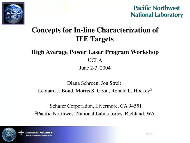
Concepts for In-line Characterization of IFE Targets . High Average Power Laser Program Workshop UCLA June 2-3, 2004 Diana Schroen, Jon Streit 1 Leonard J. Bond, Morris S. Good, Ronald L. Hockey 2 1 Schafer Corporation, Livermore, CA 94551

E N D
Concepts for In-line Characterization of IFE Targets High Average Power Laser Program Workshop UCLA June 2-3, 2004 Diana Schroen, Jon Streit1 Leonard J. Bond, Morris S. Good, Ronald L. Hockey2 1Schafer Corporation, Livermore, CA 94551 2Pacific Northwest National Laboratories, Richland, WA
The GA Plant Design Did Not Specify When Characterization Would Occur. Oil Exchange A Isopropanol Exchange Heat Curing Overcoating Micro-encapsulation Isopropanol Exchange CO2 Drying Tritium Filling B
Statistical sampling was assumed. This could be problematic because: • Statistics may not be valid for all processes. For example, variation within microencapsulation batches is the norm. • Consequences may be difficult to deal with – the chamber conditions will be very different after a “dud” than after a fire. • Instead, consider in-line automated every capsule characterization especially at points A and B. • This is the approach that PNNL is using for the TRISO fuel pellet.
Analysis (2 Views Minimum) Fail Shells Flow Through Tube Pass Point A Characterization • Characterizing a bare foam 4 mm OD capsule. • 300 micron DVB Foam Wall, • 20 - 120 mg/cc density • QA at this point reduces useless effort in overcoating step. • Less solvent waste from overcoating process • Less difficult analysis as results are not confused by overcoating. • Two possible techniques – same principle.
Water DBP Water IPA IPA BSA BSA Rinse Away BSA with IPA After Gelation Rinse Away Water with IPA Exchange into BSA Ready to Characterize A1 Optical Characterization • Optical Characterization requires several process steps and creates much solvent waste. • Benzyl Salicylate is an effective index match making characterization easier and more accurate. • DBP = Dibutyl Phthalate, IPA = Isopropyl Alcohol, BSA = Benzyl Salicylate
Water Water DBP DBP Water Water IPA After Gelation Characterize Rinse Away Water with IPA A2 Ultrasonic Characterization Ultrasonic Transducer • Ultrasonic waves couple well in 60°C aqueous solutions. • No exchanges would be required. • Non-contact Go/No Go Analysis. Measured Interfaces & Thicknesses Profile of Focused Field
Point B Characterization • Characterization of a completed target. • QA at this point reduces failure rate in the chamber. • With a shot rate of 500,000 per day even a small percentage of failures is a large number. • The concept is to do multiple characterizations to improve the probability of detecting defects. • Wall, CH + Au • DVB foam • DT ice layer
Ultrasonic Transducer Measured Interfaces & Thicknesses Profile of Focused Field DVB Sphere with Inner Deuterium Ice Layer B1 Ultrasonic Characterization • High Speed • Non-Contact • Liquid Helium is Used as Ultrasonic Couplant • Target is Inspected on-line using suite of Ultrasonic Transducers • Pulse-echo (one transducer) • Transmission (pair) • Real-time data processing • Unacceptable Targets are Ejected
Pass Fail B2 EM In-Line Characterization Throughput Up to ~ 200 particle/sec Electric Field (Dielectric Constant) Eddy Current (Conductivity & Permeability) QA/QC Meter
Development of Cryogenic Measurement Concept • Measured Properties • Concentricity, Thickness of Deuterium Ice Layer • Detection and Quantification of Non-Bond Regions or Voids • Detailed Imaging of Internal Structure The proof of cryogenic ultrasonic characterization can be done now. Heat Shield Heat Shield Heat Shield Properties of Cryogenic Fluids Fluid Acoustic Temp. Relative Velocity Attenuation (m/s) (K) Water 1480 298 22 Nitrogen 860 77 14 Neon 600 27 23 Helium 227 2 70 Helium 238 0.4 2 Acoustic Transducer Acoustic Transducer Acoustic Transducer Cryogenic Liquid Cryogenic Liquid Cryogenic Liquid Sample Sample Sample Support Frame Support Frame Support Frame Dewar Dewar Dewar
Porous Buffer Fuel Kernel Carbide Barrier Pyrolytic Carbon 100 µm PNNL is Automating QA/QC of Coated Fuel Particle • Gen IV reactors require TRISO coated fuel particles. • Developing and maintaining the TRISO coating process requires characterization of each constituent material. • Production must be ~200 particles/sec to sustain each reactor with the 109’s of particles required at refueling. • Present day QA/QC cannot meet these challenges. • Automated NDE methods are being developed. • High-speed electrical, optical, ultrasonic and X-ray methods. * R. Hockey, L.J. Bond, C. Batishko,J.N. Gray, J. Saurwein, and R. Lowden, “Advances in Automated QA/QC for TRISO Fuel Particle Production,” Proceedings of ICAPP ’04, Pittsburgh, PA USA, June 13-17, 2004; Paper 4213 The DOE-NERI Program is supporting this work involving a research team lead by the Pacific Northwest National Laboratory, with collaborators at General Atomics, Iowa State University and Oak Ridge National Laboratory.
Their Concept Is to Use Multiple Techniques. Completed targets • Sorting technology options • Optical • Ultrasonic • Electromagnetic • Use multiple on-line technologies to give rapid go/no-go sorting • Increase reliability of defect detection (POD) Reject Optical Reject Ultrasound Reject Electromagnetic ACCEPT
TRISO Coated Fuel Particle Cutaway shows coating layers Pass Fail TRISO Fuel EM In-Line Characterization Concept 800-950 µm Throughput 200 particle/sec Electric Field (Dielectric Constant) Eddy Current (Conductivity & Permeability) QA/QC Meter
EC Signal vs. Dimensions,Normal TRISO & Thin SiC Layer • Dimensions determined by X-ray analysis. • EC signal is affected primarily by conductivity & volume of each material
Capacitance of TRISO Particles with SiC Present (5) & Absent (12) • Fully coated, variable diameter particles to left. • Minus SiC layer, variable diameter particles to right. • Eddy current and electric field measurement compared for each particle. Normal TRISO Missing SiC
Conclusions • Advanced inspection technologies provide potential to give on-line accept/reject for targets at multiple points in the creation of the target. • This eliminates the assumption of statistical sampling. • Characterization can be done at cryogenic temperatures when required. • At the critical point before injection, multiple characterizations can improve probability of fielding a good target. • Proposed technologies have history of successful application, currently being developed for TRISO fuel particles.