Download
1 / 18
180 likes | 310 Views
Front end electronics for the tile HCAL prototype. Felix Sefkow DESY CALICE meeting, June 29, 2004. HCAL modules. 38 layers 30 * 220 tiles 8 * 145 tiles 8000 analogue channels in total. 1 square metre with 220 tiles. Outline. The ECAL electronics Special SiPM requirements First tests

E N D
Front end electronics for the tile HCAL prototype Felix Sefkow DESY CALICE meeting, June 29, 2004
HCAL modules • 38 layers • 30 * 220 tiles 8 * 145 tiles • 8000 analogue channels in total 1 square metre with 220 tiles Felix Sefkow
Outline • The ECAL electronics • Special SiPM requirements • First tests • Proposals • Fast digitization approach: Igor’s talk Felix Sefkow
ECAL readout overview • 10k analog channels Felix Sefkow
ECAL front end 12 lines 18x MUX 216 channels Felix Sefkow
ECAL electronics Felix Sefkow
ECAL DAQ CERC (Calice ECAL r/o card) • 8x12 ADCs, 8 MB memory (1-2k events) • DAQ rate 1 kHz peak, 100Hz average • 180 ns trigger latency 6 more HCAL boards would fit into ECAL crate Felix Sefkow
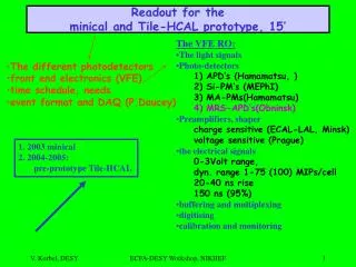
SiPM requirements • Si PM signals: • gain 106: 1 photo electron = 160 fC • MIPs ~ 25 p.e. • dyn range: Max signal = 400 pC • fast: few ns rise time pulse shape given by wave length shifter fibre • SiPMs so far used with short gates (100 ns) and QDCs • Noise rate is 2 MHz: a signal every 500 ns • dominated by 1 pixel signals • rate at kHz level with threshold at ¼ MIP • but could create pile-up with slow shaping for single p.e. signals Felix Sefkow
SiPM calibration • The MIP signal determines the energy scale • monitor overall response • scint, SiPM, FEE • LED: inject UV into scintillator: • The single photon peak spacing together with MIP and universal response function gives • saturationcorrection • gain monitoring: sensitive to temperature: Gain: 3%/K, Signal: 4%/K • few p.e. peak heights: cross talk • large LED signals: direct saturation monitoring • charge injection: electronics Felix Sefkow
Fast shaping • tests with SiPM cassete at Orsay 26ns peaking time Felix Sefkow
Slow shaping Checked: No problem for MIP ~60 ns 110 ns peaking time Felix Sefkow
Figure 1.1 Tests at MEPhI • Use FLC_PHY1 version of ECAL chip • has bypass output after preamp stage shaper output Felix Sefkow
Figure 1.2 Tests at MEPhI • Use the bypass output directly after preamp stage preamp output Felix Sefkow
Figure 1.4 Tests at MEPhI • combine FLC_PHY1 preamp with external shaping amp shaper output Felix Sefkow
Unipolar shaping: MEPhI simulations • 2 gain settings: high for calibration, low for data taking • both with long shaping times, avoiding undershoot Felix Sefkow
Proposals • Unipolar shaping • as shown by MEPhI measurements, this should allow to perform single pixel gain caibration and data taking with same shaping time • possible problem: low frequency noise (DC levels not decoupled) • Two different shaping times • for LED calibration can delay pulse, not constraint to 150 ns • take LED runs more often than MIP data • relate two scales by LED at ~MIP amplitude, and charge injection • validate with “fast” triggered MIPs • possible problem: non-linearity of gain for fast shaping ? • probably OK with proposed LED scheme (light through WLS) • Both simulated • Both implememted • unipolar with some compromise to schedule, only one gain Felix Sefkow
Front end PCB • 216 coax cables in, 1 flat cable out • layout not yet specified, to be defined next ? Felix Sefkow
Conclusion • A unified ECAL + HCAL readout scheme seems possible • Sample and Hold type solutions for SiPM r/o are found • To be done: • back-up solutions • FEE PCB • Looking forward to learn from prototype FLC_SiPM Ludovic’s talk Felix Sefkow