Download
1 / 47
470 likes | 478 Views
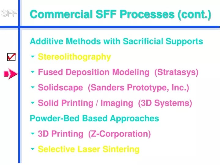
Commercial SFF Processes (cont.). Additive Methods with Sacrificial Supports Stereolithography Fused Deposition Modeling (Stratasys) Solidscape (Sanders Prototype, Inc.) Solid Printing / Imaging (3D Systems) Powder-Bed Based Approaches 3D Printing (Z-Corporation)

E N D
Commercial SFF Processes (cont.) Additive Methods with Sacrificial Supports • Stereolithography • Fused Deposition Modeling (Stratasys) • Solidscape (Sanders Prototype, Inc.) • Solid Printing / Imaging (3D Systems) Powder-Bed Based Approaches • 3D Printing (Z-Corporation) • Selective Laser Sintering
SFF: Fused Deposition Modeling Principle: • Beads of semi-liquid ABS* plastic get deposited by a head moving in x-y-plane. • Supports are built from a separate nozzle. Schematic view ==> • Key player: Stratasys: http://www.stratasys.com/ * acrylonitrile-butadiene-styrene
Single-thread Figure-8 Klein Bottle As it comes out of the FDM machine
Support = Scaffolding The areas in each layer where scaffolding is neededis calculated by “Quickslice” (Stratasys’ FDM software).
Layered Fabrication of Klein Bottle Support material
Klein Bottle Skeleton (FDM) Support removal can be tedious and painful !
Positioning for Strength • Desired part geometry • Necessary support material • Trade-offs: part strength <-> amount of support material potential breaking point partrotated thru 90°
FDM: The Software Interface StratasysQuickslice • Good “tutorial” for layered manufacturing • Offers all the knobs a professional needs • Several entry points: • STL: B-rep in triangle soup • SSL: Per-layer outline contours • SML: Actual x-y-path of head to fill each layer • Too much automated clean-up “smarts” for overlapping contours • Not convenient enough editing of contours
Newest FDM Machines (Stratasys) • The FDM Maxum™ is the fastest prototyping system offered by Stratasys, operating 50 percent faster than previous systems. • Its WaterWorks™ soluble support systems offers virtually hands-free prototyping. • Also offers a larger build volume (600x500x600 mm) able to construct a whole monitor.
Stratasys WaterWorks™ Working Adjustable Wrench • This wrench was built in assembled form, using the new “WaterWorks”soluble support system. • After the support material was dissolved, the three parts were already fully assembled and movable!
Stratasys FDM Titan System One System: • Multiple high-performance materials. • One of the largest FDM build chambers.
Stratasys: Another Material PolycarbonateRatchet Knob A fully functional mechanism built from high impact-strength material.
Fused Deposition Modeling An Informal Evaluation • Easy to use • Rugged and robust • Could have this in your office • Good transparent software (Quickslice)with multiple entry points: STL, SSL, SML • Inexpensive to operate • Slow • Think about support removal !
What Can Go Wrong ? • Black blobsat nozzle … • may topple supports … • which then leads to“Angel hair”
Error in Support Calculation • A thin downward knife-edge may be missed in thesupport calculation! Hanging “telephone wires”.
Solid Object Printing ModelMaker II (Solidscape)
SFF: Solid Object Printing ModelMaker II (Solidscape) • Alternate: { Deposition / Planarization } Steps • Build envelope: 12 x 6 x 8.5 in. • Build layer: 0.0005 in. to 0.0030 in. • Achievable accuracy: +/- 0.001 in. per inch • Surface finish: 32-63 micro-inches (RMS) • Minimum feature size: 0.010 in. • Key Player:Solidscape*: http://www.solid-scape.com/ * formerly: Sanders
SFF: Solid Object Printing Projection of 4D 120-cell, made in “jewelers wax.” (2” diam.)
SFF: Solid Scape (Sanders) An Informal Evaluation • The most precise SFF machine around • Very slow • Sensitive to ambient temperature • Must be kept running most of the time • Poor software • Little access to operational parameters Based on comments by B. G.:http://www.bathsheba.com/
SFF: Solid Object-Printing / Imaging • Droplets of a thermoplastic material are sprayed from a moving print head onto a platform surface. • Need to build a support structures where there are overhangs / bridges. • These supports (of the same material) are given porous, fractal nature. • They need to be removed (manually). • Key player: 3D Systems:http://www.3dsystems.com/
SFF: Solid Object Printing Supports made from same material, but with a fractal structure
SFF: Solid Object Printing Thermojet Printer (3D Systems) • Technology: Multi-Jet Modeling (MJM) • Resolution (x,y,z): 300 x 400 x 600 DPI • Maximum Model Size: 10 x 7.5 x 8 in (13 lb) • Material: neutral, gray, black thermoplastic: • ThermoJet 88: smooth surfaces for casting • ThermoJet 2000: more durable for handling
SFF: Solid Object Printing • That’s how partsemerge from theThermojet printer • After partial removalof the supportingscaffolding
9-story Intertwined Double Toroid Bronze investment casting from wax original made on 3D Systems“Thermojet”
Micromechanical Flying Insect Polyurethanemicro-fly, cast in silicone rubber mold, formed around wax original made on 3D Systems’“Thermojet” Ron Fearing, U.C. Berkeley
SFF: Solid Object Printing An Informal Evaluation • Fast • Inexpensive • Reliable, robust • Support removal takes some care( Refrigerate model beforehand! ) • Thermojet 88 parts are fragile • Good for investment casting
Powder-based Approaches Key Properties: • Needs no supports that must be removed! • Uniform bed of powder acts as support. • This powder gets selectively (locally) glued (or fused) together to create the solid portions of the desired part.
SFF: 3D Printing -- Principle • Selectively deposit binder droplets onto a bed ofpowder to form locally solid parts. Head Powder Spreading Printing Powder Feeder Build
3D Printing: Some Key Players • Z Corporation: http://www.zcorp.com/Plaster and starch powders for visualization models. • Soligen: http://www.zcorp.com/Metal and ceramic powdersfor operational prototypes. • Therics Inc.:http://www.therics.com/Biopharmaceutical products,tissue engineering.
3D Printing:Z Corporation The Z402 3D Printer • Speed: 1-2 vertical inches per hour • Build Volume: 8" x 10" x 8" • Thickness: 3 to 10 mils, selectable
3D Printing:Z Corporation • Digging out
Optional Curing: 30 min. @ 200ºF Keep some powder in place <-- Tray for transport
3D Printing:Z Corporation Cleaning up in the de-powdering station
3D Printing:Z Corporation The finished part • Zcorp, • 6” diam., • 6hrs.
3D Color Printing: Z Corporation The Z402C 3D Color Printer Differences compared to mono-color printer: • Color print head with: Cyan, Yellow, Magenta, Black, and Neutral. • Smaller build area. Specs: • Speed: 0.33 - 0.66 vertical inches per hour • Build Volume: 6" x 6" x 6" • Thickness: 3 to 10 mils, selectable • Color depth: 80 mils
3D Color Printing: Z Corporation Use compressed air to blow out central hollow space.
3D Color Printing: Z Corporation Infiltrate Alkyl Cyanoacrylane Ester = “super-glue” to harden parts and to intensify colors.
3D Color Printing: Z Corporation “Lizard-Frame”: Final Infiltrated Part
What Else Can Go Wrong ? • Blocked glue lines • Crumbling parts
3D Printing: Z Corporation An Informal Evaluation • Fast ! • Running expenses: moderate,(but overpriced powder) • Color print head and tubes need some care in maintenance. • Somewhat messy cleanup ! • Lot’s of dust everywhere ...