Download
1 / 52
520 likes | 524 Views
Explore the advancements in the Michelson interferometer for improved gravitational wave detection and the potential for gravitational wave astronomy. Learn about the upgrades like Fabry-Perot arm cavities, power recycling, and signal recycling.

E N D
Length Sensing and Control for anAdvanced Gravitational Wave Detector Robert Ward PhD Candidacy Caltech, 17 Jan 2006 Ward Candicacy
introduction lock acquisition modeling DC readout Ward Candicacy
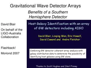
A New Window on the Universe • Once Gravitational Waves are detected, a new field of Gravitational Wave Astronomy will open up. • GW stochastic background can tell us about cosmology (Big Bang, Inflation) • Cosmic Strings • Compact binary inspirals • GRBs • Supernova collapse • Black Hole ringdowns • GW Astronomy will allow us to listen to what we cannot see. Ward Candicacy
The Michelson Interferometeras a Gravitational Wave Detector Gravitational Wavesact on freely falling masses: mirrors laser Beam splitter Dark port photodiode Antenna pattern Suspend the masses Ward Candicacy
Upgrading the Michelson Gravitational Waves are tiny: they interact very weakly with matter. Need more than a simple michelson to have a chance of detection. LASER OOM 1 km arms 10W NdYAG h = 10^-21 1 photon GWD Ward Candicacy
Upgrading the Michelson • Fabry-Perot Arm Cavities (Like having longer arms) GWD Ward Candicacy
Upgrading the Michelson • Fabry-Perot Arm Cavities (Like having longer arms) • Power Recycling (Like having a bigger LASER->lower shot noise) Initial LIGO GWD Ward Candicacy
Upgrading the Michelson • Fabry-Perot Arm Cavities (Like having longer arms) • Power Recycling (Like having a bigger LASER) • Signal Recycling (Reshape the SIGNAL) Advanced LIGO GWD Ward Candicacy
Why Signal Recycle? Why RSE? • Problem 1: If the current Initial LIGO optical configuration (power-recycled Michelson with Fabry-Perot arms) is retained in AdLIGO, the increased laser power (needed for better sensitivity in the high-frequency shot-noise-limited regime) will put intolerable thermal load on the transmissive (absorptive, lossy) optics in the power recycling cavity (BS, ITM substrates). • Solution 1: increase the finesse (optical gain) of the F-P arms, decrease the gain in the PRC. • Problem 2: Increasing the finesse of the arms causes the cavity pole frequency to decrease, leading to reduced bandwidth for GW signal. • Solution 2: resonant sideband subtraction! FP cavity Power PRM FP cavity Laser BS GW signal SEM Ward Candicacy
The Reason for AdLIGO:Initial and Advanced LIGO • Factor 10 better amplitude sensitivity • (Reach)3 = rate • Factor 4 lower frequency bound • NS Binaries: for three interferometers, • Initial LIGO: ~20 Mpc • Adv LIGO: ~300 Mpc • BH Binaries: • Initial LIGO: 10 Mo, 100 Mpc • Adv LIGO : 50 Mo, z=2 • Stochastic background: • Initial LIGO: ~3e-6 • Adv LIGO ~3e-9 Ward Candicacy
Improvement of reach with Advanced LIGO Improve amplitude sensitivity by a factor of 10x, and… Number of sources goes up 1000x! Virgo cluster LIGO I AdLIGO Ward Candicacy
AdLIGO noise curve • Fight the Fundamental Noise Sources: • Seismic • Thermal • Quantum Bench Active Seismic Isolation External Seismic Pre-Isolation Quadruple pendulum suspensions 40 kg, fused silica Test Masses 125W Laser Ward Candicacy
Caltech 40 meter prototype interferometer Objectives • Develop a lock acquisition procedure for suspended-mass detuned RSE interferometer with power recycling, preferably one that will be applicable to Advanced LIGO BS SRM PRM • Characterize and optimize optical configuration (for robust control and sensitivity) • Characterize noise mechanisms • Develop DC readout scheme • Test QND techniques • Extrapolate to AdLIGO via simulation • Prototyping will yield crucial information about how to build and run AdLIGO Bright port Dark port X arm Y arm Ward Candicacy
Bench: 40m Sensitivity Not very likely that we’ll actually detect any gravitational waves here, but hopefully we’ll learn some things about operating interferometers, especially about the quantum noise. Bench Ward Candicacy
40m DARM Optical Plant UGF • The 40m operates in a detunedRSEconfiguration, which gives rise to two peaks in the DARM transfer function: • Optical Resonance • Optical Spring Ward Candicacy
IFO DARM/CARM FWHM Carrier frequency Sideband amplitude [a.u.] slope related to spring constant fsig LSB USB frequency offset from carrier [Hz] Detune Cartoon • IFO Differential Arm mode is detuned from resonance at operating point SRC DARM • IFO Common Arm mode is detuned from resonance at intial locking point • Responses of GW USB and GW LSB are different due to the detuning of the signal recycling cavity. PRC CARM Ward Candicacy
PRM Signal Extraction Scheme • Arm cavity signals are extracted from beat between carrier and f1 or f2. • Central part (Michelson, PRC, SRC) signals are extracted from beat between f1 and f2, not including arm cavity information. • Only +f2 sideband resonates in combined PRC+SRC Carrier • Single demodulation • Arm information -f2 -f1 f1 f2 • Double demodulation • Central part information Ward Candicacy
ETMy Phase Modulation f1=33MHz f2=166MHz Ly=38.55m Finesse=1235 ITMy lsy PRM ly ITMx BS lx Lx =38.55m Finesse=1235 lsx SRM PO SP AP 5 DOF for length control Signal Extraction Matrix (in-lock, DC) 40m Common of arms Differential of arms Power recycling cavity Michelson Signal recycling cavity : L=(Lx Ly) / 2 : L=Lx Ly : l=(lx ly) / 2 =2.257m : l=lx ly = 0.451m : ls=( lsx lsy) / 2 =2.15m ETMx Laser Ward Candicacy
Lock Acquisition Ward Candicacy
What does it mean to be locked? • GW IFOs are actively-nulled instruments with narrow linear operating ranges. • Locked: All degrees of freedom are withinlinear operating range, held there by an active control system 40M single arm cavity: • = 1200 → less than 0.1% of available space offers good control signals less than 1 nm 1 ms at 1µm/s Pound-Drever-Hall error signal for a single cavity Ward Candicacy
Lock Acquisition • Gravitational Wave Interferometers do not come ‘ready to use’ • Natural state is totally uncontrolled (with nonlinear, heavily coupled signals) • Lock Acquisition is the process by which an IFO is brought from an uncontrolled state to the controlled operating point. • Should be considered during the DESIGN phase of an IFO • Money = commissioning + runtime • Can have a very large impact on duty cycle • duty cycle = events Ward Candicacy
From a Bunch of Swinging Mirrors to a Gravitational Wave Detector • AdLIGO will be much harder to lock than LIGO-1 • 4 DOFs to 5 DOFs + SRM scramble • factor 10000 smaller actuation potential • all signals come with offsets • Prototyping can address: • Bootstrapping problem • LIGO I set itself a difficult problem by deciding to lock ONLY at the operating point. • It’s better to cheat (offsets, misalignments, etc). • GOAL: A robust, reliable, and easily diagnosable LA procedure. • Less time spent locking = more time for science! Ward Candicacy
40m Lock Acquisition part I: Off-resonant lock scheme for a single cavity Transmitted light is used as Resonant Lock Off-resonant Lock point 10x higher finesse than LIGO Ward Candicacy
40m Lock acquisition procedure (v 1.0) Start with no DOFs controlled, all optics aligned. ITMy 166MHz ITMx 13m MC BS 33MHz PRM PO DDM SP33 SRM SP166 SP DDM AP166 AP DDM Ward Candicacy
1/sqrt(TrY) 40m Lock acquisition procedure (v 1.0) DRMI + 2arms with offset Average wait : 3 minute (at night, with tickler) ITMy 166MHz ITMx 13m MC 1/sqrt(TrX) BS 33MHz PRM T=7% PO DDM SRM SP166 SP33 T=7% I SP DDM Q AP166 AP DDM Ward Candicacy
-1 40m Lock acquisition procedure (v 1.0) Short DOFs -> DDM DARM -> RF signal CARM -> DC signal 1/sqrt(TrX)+ 1/sqrt( TrY) CARM -> Digital CM_MCL servo CARM + + DARM ITMy 166MHz ITMx 13m MC BS 33MHz PRM PO DDM SRM SP33 SP166 SP DDM To DARM AP166 AP DDM AP166 / sqrt(TrX+TrY) Ward Candicacy
-1 40m Lock acquisition procedure (v 1.0) Reduce CARM offset: 1. Go to higher ARM power 2. Switch on AC-coupled analog CM_AO servo, using REFL DC as error signal. 3. Switch to RF error signal (POX) at half-max power. 4. Reduce offset/increase gain of CM_AO. DARM ITMy 166MHz ITMx 13m MC BS SP166 33MHz PRM PO DDM SRM SP33 SP DDM To DARM REFL AP166 AP DDM AP166 / (TrX+TrY) Ward Candicacy
DARM TFs as CARM offset is reduced Ward Candicacy
Other Lock Acquisition Schemes Alternative Locking Schemes are on the way! • Deterministic Locking: • Locking occurs in stages, with each stage having robust control • Each stage can (and should) lock on the first ‘fringe’, or be robust to fringes. • Transitions between stages are smooth and robust. • Advantages: • Easier to diagnose problems • Should require less actuation potential • If we can lock a single arm cavity, we can lock the IFO. 40M: AdLIGO 7 mN 1.3 kg test mass f/m = 5 20 µN 40 kg test mass f/m =5e-4 Ward Candicacy
Digital length control system D/A D/A AP166 A/D mixer Output to suspensions Feedback filters Demodulated signal from PD Ward Candicacy
Compensating the resonances Compensation Filters for the two resonances associated with the signal cavity: UGFs ~ 250Hz Optical Opto-mechanical DARM CARM Ward Candicacy
Dynamic compensation filterfor CARM servo Optical gain of CARM Open loop TF of CARM • Optical gain (normalized by transmitted arm power) shows moving peaks due to reducing CARM offset. • We have a dynamic compensative filter having nearly the same shape as optical gain except upside down. Designed using FINESSE. • Open loop transfer function has no phase delay in all CARM offset. Ward Candicacy
CARM optical springs • Solid lines are from TCST • Stars are 40m data • Max Arm Power is ~80 • Also saw CARM anti-springs, but don’t have that data Ward Candicacy
Mode healing/injuring at Dark Port Negative spring constant with optical spring Positive spring constant with no optical spring Carrier power at DP is 10x smaller • Repeatable • The same alignment quality Ward Candicacy
Modeling Ward Candicacy
What’s modeling all about? • With 5 DOFs and detuned cavities, Advanced LIGO will have a very complicated optical configuration, with a rich frequency response. We need good modeling tools, and we need to use them in order to understand AdLIGO, before it is built. • We already rely heavily on modeling at the 40m because the configuration is so complicated. • Building a prototype, and then using modeling to extrapolate, is a good way to understand AdLIGO in advance! Ward Candicacy
Optickle: Frequency Domain IFO Simulation • Optickle is a new frequency domain IFO modeling tool: • Written in Matlab • Matlab allows easy integration to other modeling efforts (a frequency-domain e2e, like LinLIGO) • Easily Extensible • Uses Matlab classes for generality • Uses the methods outlined in T. Corbitt et al: “Mathematical framework for simulation of quantum fields in complex interferometers using the two-photon formalism” (LIGO-P030071-00R) to calculate the IFO opto-mechanical frequency response. • Designed for concrete units (Watts, meters, Hz) Ward Candicacy
Optickle example: detuned FP cavity • Response of front mirror to back mirror ‘excitation’ • 1 nm detune • finesse ~ 1200 Ward Candicacy
Optickle Example: AdLIGO • Easy to create a frequency dependent coupling matrix, useful for, e.g., estimating the contribution of loop noise to DARM. • This plot is Open Loop. Closed loop coming soon! Ward Candicacy
Optickle v. the 40m Optickle Modeling Ward Candicacy
DC Readout Ward Candicacy
Quantum Noise: Heterodyne vs Homodyne Quantum noise curves plotting using formulas in: A. Buonanno, Y. Chen, N. Mavalvala, “Quantum noise in laser-interferometer gravitational-wave detectors with a heterodyne readout scheme” PHYSICAL REVIEW D 67,122005 2003 Ward Candicacy
What is DC Readout and how does it relate to Homodyne Detection? DC Readout is Homodyne detection, using light circulating in the interferometer as a local oscillator. Advantage: LO light has been filtered by the <1Hz coupled cavity pole Disadvantage: limited ability to control homodyne phase OMC Ward Candicacy
Technical noise sensitivity Ward Candicacy
RF vs DC • Phase modulate the input light • RF sidebands act as local oscillator for GW signal, after passing through (unstable) recycling cavity(ies) • GW signal is an audio frequency sideband of RF photocurrent • Mix GW signal down to near-DC • Acquire GW signal at DC with ADC • Eliminate the RF sidebands at Dark Port with an Output Mode Cleaner • Eliminate junk light at the Dark Port with Output Mode Cleaner • Carrier light acts as a local oscillator • GW signal is an audio frequency photocurrent • Acquire GW signal at DC with ADC Ward Candicacy
LIGO I GW parallel to DC offset fringe offset β Loss mismatch Some linear component No slope Making the DClocal oscillator • Two components • Carrier field due to loss differences (not controllable? TCS?) • Carrier field due to dark fringe offset (controllable) • An output mode cleaner should take care of the rest. (RF sidebands, junk light) • Loss mismatch component • Average arm round trip loss: 200 ppm • Difference between arms: 50 ppm • Output power due to mismatch: 20 µW • Detection angle, β • Tuned by adjusting fringe offset • Can tune from 0-80 deg with 0-10pm of DARM offset • 1 mW LO • Angle of GW is frequency dependent in detuned RSE Detuned RSE: GW signal gets f-dependent phase shift in SRC Ward Candicacy
Laser Intensity Noise • calculated using rsenoise • 10 pm DARM offset for DC • 1e-13m residual L- RF: noise sidebands of RF sidebands beat against residual length offset DC: dark port power proportional to input power Radiation pressure effects not included Ward Candicacy
Laser Frequency Noise • calculated using rsenoise • 10 pm DARM offset for DC • 1e-13m residual L- RF: frequency noise sidebands of RF sidebands beat against static carrier contrast defect DC: Arm cavity pole imbalance couples carrier frequency noise to dark port Radiation pressure effects not included Ward Candicacy
OMC Properties The Output Mode Cleaner filters the light coming out of the dark port, cleaning away the junk and transmitting the GW-signal containing TEM00 mode of the carrier Ward Candicacy
OMC design in SolidWorks • Small number of pieces • HV compatible • some glue near the PZT mirror • Mirrors mounted mechanically, on silver washers (no glue) • ALGOR FEA: lowest mech resonance at ~770 Hz • Construct out of well-damped material, to minimize effect of resonances: Copper • All high-quality (REO super-polished and coated) mirrors available from LIGO lab spares (the 4th HR mirror, 0o incidence, came from Newport) Mike Smith Ward Candicacy