Download
1 / 29
450 likes | 801 Views
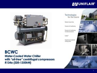
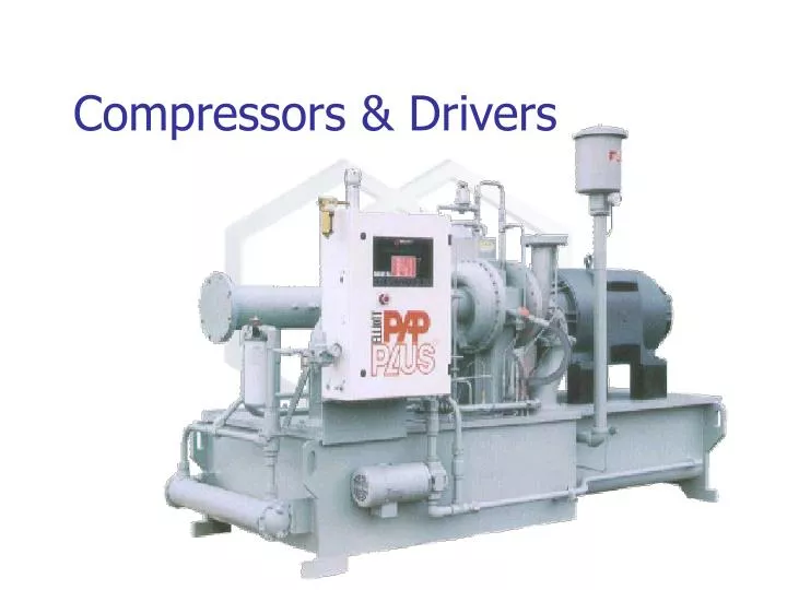
Compressors & Drivers. Compressor. Types Dynamic Centrifugal Ejector Displacement Positive Diplacement Issues Control Seals. MOTIVE FLUID. DISCHARGE. SUCTION. Axial. SUCTION. DISCHARGE. ESTIMATOR CHOICES. Selection Chart. ESTIMATOR - Compressor Input. Fluid Power Calculation.

E N D
Compressor • Types • Dynamic • Centrifugal • Ejector • Displacement • Positive Diplacement • Issues • Control • Seals
MOTIVE FLUID DISCHARGE SUCTION
SUCTION DISCHARGE
Fluid Power Calculation • Fluid Static Head -> approx. 0 • Include Piping Frictional Losses of 10 psi per segment between equipment. • Exchanger Losses per simulation assumptions • Control Valve losses (15 psi for our 500 psig system - but eliminate if possible?). • Fluid Flow • Efficiency (75% to 80%)
PRO II Output Seals Normally Limited to 350 °F (180 °C)
Compression Ratio • P2 / P1 (absolute pressures) • Not required in our calcs for cost but if excessive are an indication that a multistage compressor would be required (usually confirmed by outlet temperature).
Centrifugal Compressors and Fans Performance & Controls Diff Press Okay Surge Inlet Volumetric Flow Rate
For constant discharge pressure systems (most common). Variations in process flow rate are controlled through the “inlet valve” Centrifugal - Control Inlet Vane Changes The Flow vs DP Curve of the Compressor
Centrifugal - Control Surge Line Diff Press Open Inlet Valve Closing Inlet Valve Inlet Volumetric Flow Rate
Centrifugal - Control • At the point where further restriction in the inlet valve would cause surging other controls are required. • Usually • Blow Off • Recirculation
Centrifugal - Control • Blow Off Blow Off Inlet Blow Off Valve Disch
Centrifugal - Control • Recirculation Inlet Disch
Centrifugal - Control • Variable Speed • Used on the smaller compressors for energy efficiency Diff Press High RPM Low RPM Inlet Volumetric Flow Rate
Drives For Pumps and Compressors T.E.F.C.
TEFC Air Flow seal bearing
Enclosures “protected” from outside environment allows free ambient room air to cool windings drip proof guarded weather protected “Totally Enclosed Fan Cooled” TEFC most common motor used - isolated from the free exchange of outside air Explosion Proof - designed to isolate surroundings from ignition sources such as sparking or high temperatures inside the motor Electric Drives
Performed by electrical and process engineers Process of classification identifies processes that have explosion potential flammable liquids, gases, vapors, combustible dust, or ignitable fibers or flyings based on flash point, operating temperature etc. Identifies distances from process that are ‘safe’ identifies equipment and instrumentation enclosure requirements i.e. Explosion proof Electrical Area Classification
Our Compressor • What composition we have going through compressor? • Is the material a fire/explosion hazard (operated above it’s flash point) ? • Do we have an explosion potential if it leaks out of compressor? • What drive type should we choose?