Download
1 / 32
610 likes | 2.02k Views
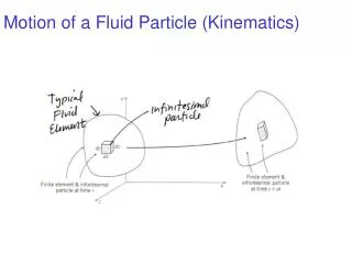
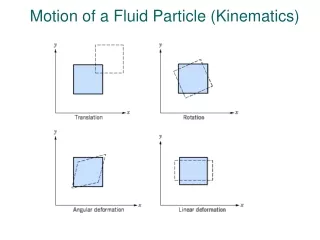
FLUID KINEMATICS. BY GP CAPT NC CHATTOPADHYAY. Fluid Kinematics. Velocity Field Continuity Equation. Fluid Kinematics. What is fluid kinematics? Fluid kinematics is the study on fluid motion in space and time without considering the force which causes the fluid motion.

E N D
FLUID KINEMATICS BY GP CAPT NC CHATTOPADHYAY
Fluid Kinematics • Velocity Field • Continuity Equation
Fluid Kinematics What is fluid kinematics? • Fluid kinematics is the study on fluid motion in space and time without considering the force which causes the fluid motion. • According to the continuum hypothesis the local velocity of fluid is the velocity of an infinitesimally small fluid particle/element at a given instant t. It is generally a continuous function in space and time.
Velocity Field • Eulerian Flow Description • Lagrangian Flow Description • Streamline • Pathline • Streakline
In the Eulerian Method • The flow quantities, like p,u,T,ρ are described as a function of space and time without referring to any individual identity of the fluid particle (ALL PARTICLES ARE CONSIDERED)
Streamline • A line in the fluid whose tangent at a point is parallel to the instantaneous velocity vector at a given instant t. So, the tangent indicates the velocity at that point. • The family of streamlines at time t are solutions of dx/ u= dy/v= dz/w (so, the equations of stream lines are……..) • Where u,v,w are functions of x,y,z,t and u,v,w are velocity components in the respective direction
TYPES OF FLOW • Steady flow : the streamlines are fixed in space for all time. d(k)/dt=0 (NO CHANGE W.R.T. TIME) • Unsteady flow : the streamlines are changing from instant to instant. d(k)/dt=0
Flow Dimensionality • Most of the real flows are 3-dimensional and unsteady : u (x,y,z,t) • For many situations simplifications can be made : 2-dimensional unsteady and steady flow u (x,y,t) 1-dimensional unsteady and steady flow u (x,t)
In the Lagrangian Method • The flow quantities are described for each individually identifiable fluid particle moving through flow field of interest. The position of the individual fluid particle is a function of time. (STUDY OF EACH PARTICLE IS CUMBERSOME)
Pathline • A line traced by an individual fluid particle : r(t) • For a steady flow the path lines are identical with the streamlines.
Streakline • A streak line consists of all fluid particles in a flow that have previously passed through a common point. Such a line can be produced by continuously injecting marked fluid (smoke in air, or dye in water) at a given location. (locus of particles at a particular station) • For steady flow : The streamline, the path line, and the streak line are the same.
Stream-tube and Continuity Equation • Stream-tube • Continuity Equation of a Steady Flow
Stream-tube • Is the surface formed instantaneously by all the streamlines that pass through a given closed curve in the fluid.
DEFINITIONS • LAMINAR: FLOW IS LAMINAR IFPARTICLES MOVE IN DEFINED LAYERS IN DEFINED PATH,(NO CROSSING OF LAYERS, flow on ac skin) • TURBULENT: PARTICLES MOVE IN A ZIG- ZAG WAY(PARTICLES CROSS EACH OTHER/ LAYERS, high speed flow in pipe)
DEFINITIONS • ROTATIONAL: PARTICLES ROTATE ABOUT OWN AXIS (FLOW NEAR SOLID BOUNDARY, ROTATING TANK) • IRROTATIONAL : PARTICLES MAINTAIN SAME ORIENTATION(FLOW ON LOW SPEED AEROFOIL)
STREAM FUNCTION & VELOCITY POTENTIAL FUNCTION • STREAM FUNCTION (Ψ) A FUNCTION IN THE 2 D FLOW FIELD WHOSE DERIVATIVES REPRESENT VELOCITIES ALONG RESPECTIVE AXES. DIFFERENCE BETWEEN TWO NEIGHBOURING STREAM FUNCTIONS INDICATE VOLUMETRIC FLOW i.e. Ψ1 – Ψ2= VOL THROUGH THE STREAM LINES. ALSO, u = ∂ ψ/∂ y and v= - ∂ Ψ/∂ x, • VELOCITY POTENTIAL FUNCTION (Φ) A SCALER FUNCTION WHOSE NEGATIVE DERIVATIVES REPRESENT RESPECTIVE VELOCITIES. IT INDICATES IRROTATIONAL OR P0TENTIAL FLOW. MATHEMATICALLY, u = - ∂ Φ /∂ x and v = - ∂ Φ /∂y, w = - ∂ Φ/∂z
DEFINITIONS • Continuity • Matter cannot be created or destroyed - (it is simply changed in to a different form of matter). This principle is know as the conservation of mass and we use it in the analysis of flowing fluids. • The principle is applied to fixed volumes, known as control volumesFor steady flow - Mass entering per unit time = Mass leaving per unit time
CONTINUITY A liquid is flowing from left to right and the pipe is narrowing in the same direction. By the continuity principle, the mass flow rate must be the same at each section - the mass going into the pipe is equal to the mass going out of the pipe. So we can write
Continuity Equation of a Steady Flow • For a steady flow the stream-tube formed by a closed curved fixed in space is also fixed in space, and no fluid can penetrate through the stream-tube surface, like a duct wall.
Considering a stream-tube of cylindrical cross sections with velocities perpendicular to the cross sections and densities at the respective cross sections and assuming the velocities and densities are constant across the whole cross section , a fluid mass closed between cross section 1 and 2 at an instant t will be moved after a time interval dt by to the cross section 1’ and 2’ respectively. Because the closed mass between 1 and 2 must be the same between 1’ and 2’, and the mass between 1’ and 2 for a steady flow can not change from t and t+dt, the mass between 1 and 1’ moved in dt, i.e must be the same as the mass between 2 and 2’ moved in the same time dt i.e :
Therefore the continuity equation of steady flow : • Interpretation : The mass flow rate • through a steady stream-tube or a duct. • For incompressible fluid with : • Interpretation : The volume flow rate • From the continuity equation for incompressible fluid : • for a stream-tube.
DISCHARGE • Discharge and mean velocity • If we know the size of a pipe, and we know the discharge, we can deduce the mean velocity AS Um= Q/A • If the area of cross section of the pipe at point X is A, and the mean velocity here is Um. During a time t, a cylinder of fluid will pass point X with a volume Q. The volume per unit time (the discharge) will thus be Discharge in a pipe
DEFINITIONS • Mass flow rate– MASS/ TIME • Volume flow rate – (Discharge) • Simply called flow rate The symbol normally used for discharge is Q. The discharge is the volume of fluid flowing per unit time. Multiplying this by the density of the fluid gives us the mass flow rate. Consequently, if the density of the fluid for example is 850 and time is 1 sec for 0.857 cubic m then:
Derivation of the Continuity Equation • Let’s start with a small, fixed volume of fluid somewhere in the middle of a flow stream. This elemental volume has sides of lengths Dx, Dy and Dz (see Figure 1). The rate of mass entering a face is the product of the density, the fluid velocity and the face area. For example, on the side facing the reader, the density (r) is multiplied by the velocity in the x direction (u) and the area of the face Dy Dz. Thus, the mass flux entering the volume through this face is
CONTINUITY EQUATION • The mass leaving the volume on the opposite side of the volume is again the product of density, velocity and area, but the density and velocity may have changed as the fluid passed through the volume. We will express these changes as small quantities (since our volume is small enough), i.e., ρ+ Δρ and u + Δ u. The mass flux leaving that face is thus • Performing the same analysis on the mass entering the volume through the other faces of the volume gives us • Similarly, the mass fluxes leaving the volume on the opposite faces are
CONTINUITY EQUATION • All of these added together must equal the mass of fluid accumulating in the volume, • Putting all of these together, we have
CONTINUITY EQUATION • Multiplying out the quantities in parentheses results in the cancellation of some terms and the appearance of higher-order terms such as Δρ, ΔuΔx ΔyΔz. Since the quantities preceded by Δ are very small, products of these quantities will be extremely small, depending on the number of Δ terms included in the product. The terms with four of these will be much smaller than the terms with only three Δ terms. Thus, all higher order terms are neglected. This leaves • which, when divided by and rearranged, yields
CONTINUITY EQUATION The application of basic calculus (taking the limit as Δt tends to 0) allows us to write this equation as The Continuity Equation may be simplified for some common flow situations as follows. If the fluid may be treated as incompressible (as is the case with water or in low velocity air flows), the density will be constant. The Continuity Equation then becomes
CONTINUITY • Another example of the use of the continuity principle is to determine the velocities in pipes coming from a junction. Total mass flow into the junction = Total mass flow out of the junction r1Q1 = r2Q2 + r3Q3 When the flow is incompressible (e.g. if it is water) r1 = r2 = r
PROBLEM • If pipe 1 diameter = 50mm, mean velocity 2m/s, pipe 2 diameter 40mm takes 30% of total discharge and pipe 3 diameter 60mm. What are the values of discharge and mean velocity in each pipe?
Practice numericals • As discussed