Download
1 / 60
600 likes | 982 Views
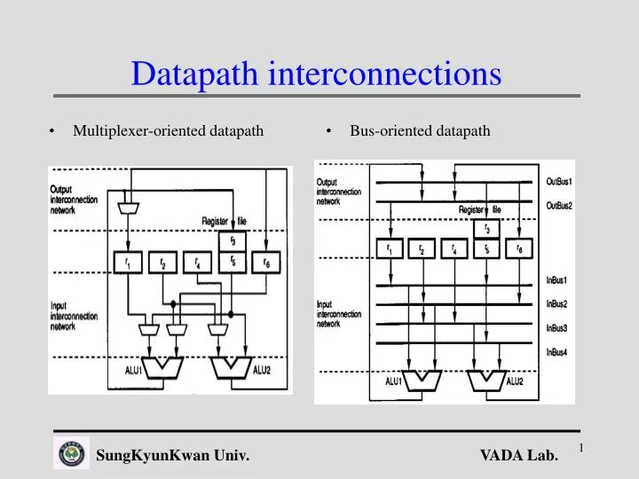
Multiplexer-oriented datapath. Bus-oriented datapath. Datapath interconnections. Sequential Execution. Example of three micro-operations in the same clock period. Insertion of Latch (out). Insertion of latches at the output ports of the functional units. Insertion of Latch (in/out).

E N D
Multiplexer-oriented datapath Bus-oriented datapath Datapath interconnections SungKyunKwan Univ.
Sequential Execution • Example of three micro-operations in the same clock period SungKyunKwan Univ.
Insertion of Latch (out) • Insertion of latches at the output ports of the functional units SungKyunKwan Univ.
Insertion of Latch (in/out) • Insertion of latches at both the input and output ports of the functional units SungKyunKwan Univ.
Overlapping Data Transfer(in) • Overlapping read and write data transfers SungKyunKwan Univ.
Overlapping of Data Transfer (in/out) • Overlapping data transfer with functional-unit execution SungKyunKwan Univ.
Scheduled DFG Graph model Lifetime intervals of variable Clique-partitioning solution Register Allocation Using Clique Partitioning SungKyunKwan Univ.
Left-Edge Algorithm • Register allocation using Left-Edge Algorithm SungKyunKwan Univ.
Sorted variable lifetime intervals Five-register allocation result Register Allocation: Left-Edge Algorithm SungKyunKwan Univ.
Register Allocation Allocation : bind registers and functional modules to variables and operations in the CDFG and specify the interconnection among modules and registers in terms of MUX or BUS. Reduce capacitance during allocation by minimizing the number of functional modules, registers, and multiplexers. Register allocation and variable assignment can have a profound impact on spurious switching activity in a circuit Judicious variable assignment is a key factor in the elimination of spurious operations SungKyunKwan Univ.
Effect of Register Sharing SungKyunKwan Univ.
Two Variable Assignments SungKyunKwan Univ.
Spurious Computing SungKyunKwan Univ.
Minimizing Spurious Computing SungKyunKwan Univ.
Effect of Register Sharing on FU • For a small increase in the number of registers, it is possible to significantly reduce or eliminate spurious operations • For Design 1, synthesized from Assignment 1, the power consumption was 30.71mW • For Design 2, synthesized from Assignment 2, the power consumption was 18.96mW @1.2-m standard-cell library SungKyunKwan Univ.
Operand sharing • To schedule and bind operations to functional units in such a way that the activity of the input operands is reduced. • Operations sharing the same operand are bound to the same functional unit and scheduled in such a way that the function unit can reuse that operand. • we will call operand reutilization (OPR) the fact that an operand is reused by two operations consecutively executed in the same functional unit. SungKyunKwan Univ.
Two scheduling and bindings SungKyunKwan Univ.
Power Saving by OPR SungKyunKwan Univ.
Results obtained by applying the operand-sharing technique. SungKyunKwan Univ.
Loop unrolling • The technique of loop unrolling replicates the body of a loop some number of times (unrolling factor u) and then iterates by step u instead of step 1. This transformation reduces the loop overhead, increases the instruction parallelism and improves register, data cache or TLB locality. SungKyunKwan Univ.
Loop Unrolling Effects • Loop overhead is cut in half because two iterations are performed in each iteration. • If array elements are assigned to registers, register locality is improved because A(i) and A(i +1) are used twice in the loop body. • Instruction parallelism is increased because the second assignment can be performed while the results of the first are being stored and the loop variables are being updated. SungKyunKwan Univ.
Loop Unrolling (IIR filter example) loop unrolling : localize the data to reduce the activity of the inputs of the functional units or two output samples are computed in parallel based on two input samples. Neither the capacitance switched nor the voltage is altered. However, loop unrolling enables several other transformations (distributivity, constant propagation, and pipelining). After distributivity and constant propagation, The transformation yields critical path of 3, thus voltage can be dropped. SungKyunKwan Univ.
Loop Unrolling for Low Power SungKyunKwan Univ.
Loop Unrolling for Low Power SungKyunKwan Univ.
Loop Unrolling for Low Power SungKyunKwan Univ.
Loop Unrolling for OPR SungKyunKwan Univ.
DFG after Loop Unrolling The estimated power-consumption reduction is now: obtaining a reduction of 9.4%. SungKyunKwan Univ.
Operand Retaining • An idle functional unit may have input operand changes because of the variation of the selection signals of multiplexers. • The operand-retaining technique attempts to minimize the useless power consumption of the idle functional units. SungKyunKwan Univ.
Spurious 연산을 최소화 f SungKyunKwan Univ.
Minimize the useless power consumption of idle units • (a) with a proper register binding that minimizes the activity of the functional units • (b) by wisely defining the control signals of the multiplexors during the idle cycles in such a way that the changes at the inputs of the functional units are minimized (this may result in defining some of the don't care values of the control signals) [RJ94] • (c) latching the operands of those units that will be often idle. SungKyunKwan Univ.
(C) latching the operands • It consists of the insertion of latches at the inputs of the functional units to store the operands only when the unit requires them. Thus, in those cycles in which the unit is idle no consumption in produced. • The control unit has to be redesigned accordingly, in such a way that input latches become transparent during those cycles in which the corresponding functional unit must execute an operation. • Similar to putting the functional units to sleep when they are not needed through gated-clocking strategies [CSB94,BSdM94, AMD94]. SungKyunKwan Univ.
LMS filter Example • The power consumption generated by the idle units (useless consumption) is: • the power consumption because of the useful calculations (useful consumption) is: The estimated reduction in power consumption is: reduction of 34%. SungKyunKwan Univ.
레지스터 할당을 위한 가중치와 캐패시티 입력( input ) : V, 레지스터 공유를 위한 네트워크 출력( output ) : 분리된 V개의 경로 W = - ( M - Wa*N ) : 에지 가중치 Wa : 두 노드간의 스위칭 확률 N : 스위칭 확률을 정수화하는 값 M : Wa * N의 최대값과 크거나 같은 정수 L : W의 최대값과 크거나 같은 정수 V : 레지스터의 갯수) Cij=1, Bij=L Cij=1, Bij=W SungKyunKwan Univ.
최소 비용 흐름 알고리즘(Minimum Cost Flows)의 목적함수와 제한조건 Minimize Z= SungKyunKwan Univ.
최소 비용 흐름 알고리즘 단계 1: flow = 0; 단계 2 :네트워크 상에서 존재하는 흐름에 의해 결정되는 변형된 비용 Bij*를 다음과 같이 정의한다. 단계 3 : 단계 2에서 변형된 비용으로 S에서 T까지의 최단 경로 알고리즘을 사용하여 개의 flow를 그경로를 통하여 보낸다. = min (1, 2) 1 = 모든 정방향 에지의 min{Cij - Xij} 2 = 모든 역방향 에지의 min{Xij} 단계 4: 현재흐름의 양을 만큼 증가시키고 단계 2로 돌아간다. 단계 5: 현재흐름의 양이 V일때까지 위 단계를 반복한다. SungKyunKwan Univ.
레지스터 호환 그래프에서 네트워크 형성 호환가능 그래프 노드 분리 전의 네트워크 형성 SungKyunKwan Univ.
노드분리와 알고리즘 적용 노드 분리 후의 네트워크 형성 알고리즘 적용 결과 SungKyunKwan Univ.
적용 결과 PATH 1 : S-a-e-f-T REG1 : a, e, f PATH 2 : S-b-T REG2 : b PATH 3 : S-c-g-T REG3 : c, g PATH 4 : S -d-T REG4 : d SungKyunKwan Univ.
저전력을 위한 리소스 할당 방법 두 연산자를 공유시 발생하는 일련의 입력 (a,e) +(b, b), (a,b)+(b+e) 중 작은 경우 선택 SungKyunKwan Univ.
변수의 저장에 따른 멀티플렉서의 증가와 감소 SungKyunKwan Univ.
리소스 할당을 위한 가중치와 캐패시티 입력( input ) : V, Network for resource sharing 출력(output ) : 분리된 V개의 경로 W : -[ M - ( Waí*N + Wmux*K ) ] ( edge weight ) Wmux : 연결 구조 가중치 K : 정규화하기 위한 상수 Wmux 0: 변수 i, j가 같은 레지스터에 할당되고 모듈의 동일 입력단으로 할당될시 : 1: 변수 i, j가 다른 레지스터에 할당되고 모듈의 동일 입력단으로 할당될시 V : 리소스의 수 Cij=1, Bij=L Cij=1, Bij=W SungKyunKwan Univ.
리소스 할당을 위한 최소 흐름 비용 알고리즘 적용 과정 노드 분리 전의 네트워크형성 호환 가능 그라프 PATH 1 : S-1-2-T adder 1 : +1 , +2 PATH 2 : S-3-T adder 2 : +3 노드 분리 후의 네트워크 형성 SungKyunKwan Univ.
레지스터와 리소스 할당 후의 최종 데이터 경로 SungKyunKwan Univ.
실험 과정 SungKyunKwan Univ.
스위칭율 계산 ( Hamming Distance ratio , Wsa) • CDFG 기능적 시뮬레이션 • 두 변수의 exclusive-OR • bit-width로 정규화 • 논리 수준이나 레이아웃 수준 보다 빠른 측정 SungKyunKwan Univ.
벤치마크 회로의 특성 Resource allocation +(2), *(2), reg(7) +(2), *(2), reg(7) +(2), *(2), reg(7) +(2) *(2),sub(1), reg(7) SungKyunKwan Univ.
실험 결과 SungKyunKwan Univ.
Cascade Filter SungKyunKwan Univ.
Cascade Filter Scheduling SungKyunKwan Univ.
Infinite Impulse Response Filter SungKyunKwan Univ.