Download
1 / 7
120 likes | 495 Views
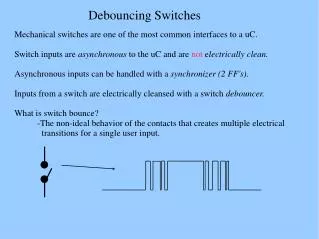
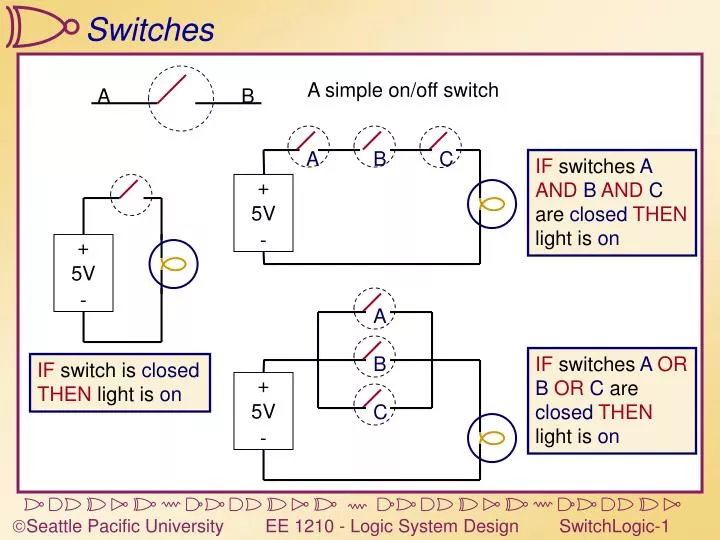
A simple on/off switch. A. B. A. B. C. + 5V -. + 5V -. A. B. + 5V -. C. Switches. IF switches A AND B AND C are closed THEN light is on. IF switches A OR B OR C are closed THEN light is on. IF switch is closed THEN light is on. A. A. A. No Connection (Open).

E N D
A simple on/off switch A B A B C + 5V - + 5V - A B + 5V - C Switches IF switches AANDBANDC are closedTHEN light is on IF switches AORBORC are closedTHEN light is on IF switch is closedTHEN light is on
A A A NoConnection(Open) PoorConnection(Resistor) GoodConnection(A wire) B B B +5V +5V +5V +5V +5V Poor Good Poor C B A 0V 0V +5V +5V Good 0V None None 0V 0V 0V Don’t do this! Good winsover None Poor winsover None Good winsover Poor A Few Words About Resistors For our purposes, we can use a very simple model of resistors: Consider these combinations:
Control A simple on/off switch with control A B Controlling Switches Threshold If Control is > 2.5V, switch is closed otherwise, switch is open. Note: Assume switches are always closed with highervoltage, open with lower voltage.
5V 5V 5V Vout=0 Vout=5 Vout Vin Vin=5 Vin=0 GND = 0V GND = 0V GND = 0V Vin switchVout 0V open 5V 5V closed 0V Vin Vout A circuit using switches Inverter
Vout Vin Vmid Vout 0V 5V 0V 5V 0V 5V Vmid Vout Vin Vin Vout Buffer Using Outputs as Inputs VCC=5V Vmid Vin
A VCC C B VA VB Vout 0V 0V 5V 0V 5V 5V5V 0V 5V5V 5V 0V Vout NAND gate VA VB A A C C B B AND gate Some more Switch Logic Vout is 0V only if VAAND VB are both 5V
VCC ABC L L H L H LH L LH H L C A B A C B A A C C OR gate B B Even more Switch Logic L = 0V, H = 5V NOR gate C is L if A OR B is H