Download
1 / 16
160 likes | 297 Views
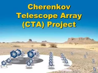
Array Trigger for CTA-US MSTs. John Anderson Karen Byrum Gary Drake Frank Krennrich Amanda Weinstein.

E N D
Array Trigger for CTA-US MSTs John Anderson Karen Byrum Gary Drake Frank Krennrich Amanda Weinstein Feb.252012 CTA-US Meeting, SLAC Frank Krennrich
Purpose and Concept of the Array Trigger • Layout and Implementation. • Specifications and Interfaces. • Technology. Feb.252012 CTA-US Meeting, SLAC Frank Krennrich
Cosmic-Ray Shield proton -ray di
Cosmic-Ray Shield proton Cut -ray di Credit: M. Schroedter
Cosmic-Ray Shield - 36 telescope array - FoV = 8 deg. - analysis based on trigger map Proton rejection ~ 90% g-ray acceptance ~ 90% Cut Conclusion: An order of magnitude cosmic-ray rate reduction at the hardwaretrigger level, while keeping 90% of g-rays, makes for an attractive option to deal with dead time & data rates!
Array Trigger: Do we need it? depends on: - dead time of readout system - success of other techniques to reduce data partial readout (Colibri) zero suppression data (pulse shape) fitting compression techniques But may not be sufficient or undesirable: - factor of 10 suppression at the trigger level (soft cut) will alleviate dead time problems, minimally affect calibration data and may allow a more complete recording of g-ray events. - allow to use large effective area of MST array at low energies, thus provide synergies with LST array (50 – 200 GeV). - bright regions of sky may cause large telescope rate fluctuations - yet allow pre-scaling and pass-through of muons. - allow in-situ performance tests of individual cameras (Amanda’s talk)
Array Trigger Concept: strawman • possible MST array • spacing d = 150 m • each telescope is • part of a sub-array • of 9 telescopes • each telescope • decides on its own • to issue a trigger • considers trigger • information from its • neighbors! <telescope multiplicity> ≈ 5
Array Trigger Concept Latency Dt: Assumption: horizontal shower
Array Trigger Concept L4 Camera • Coincidence • with at least N-neighbor • telescopes L3 L1.5 L2 Time Stamps Corrected (up to 9 tel.) Image Data Pixel Data • Data • collector • timing • corrections - n-fold coincidence of neighbor pixels • - Pattern • Trigger • Image • calculations L2’ Time Stamp Disc. L5 Initiate analysis Time Stamp Clock Distrib. Clock Distrib. Image Data • stereo analysis • e.g., parallaxwidth • calculation Image Data Interface with camera backplane Time Stamp Clock Distrib. Telescopes Feb.252012 CTA-US Meeting, SLAC Frank Krennrich
Array Trigger Implementation Modular camera concept Trigger sub-field NEIGHBOR DATA (MOMENTS) NEIGHBOR Array Trigger L2 TRIG BACKPLANE Sect. 1 NEIGHBOR READ DATA TRIG CLK L1.5 CLK NEIGHBOR 8 deg / 80cm / 11328 pixels 0.067 deg/pixel (4 arcmin) 177 MAPMTs / camera … • approx. 12k pixels • Target ASIC with 1 Gsps • memory depth 16 msec • maximum readout rate 10 kHz • single telescope trigger rate < 10 MHz Array trigger module Feb.252012 CTA-US Meeting, SLAC Frank Krennrich
Array Trigger Implementation Credit: Jim Buckley
Array Trigger Implementation DACQ FPGA TRIG Mezzanine Board L1.5 TRIG FPGA L4 Array coincidence L2 Camera Pattern trigger & image parameters L3 Data collector T-corrections L5 Stereo Analysis
Array Trigger Implementation Backplane DACQ FPGA ARRAY TRIGGER TRIG Mezzanine Board L1.5 TRIG FPGA L1.5 TRIG Info T-stamp Pixel # Camera/ Array Trigger L1.5 TRIG Info L2 Test data L4 Array coincidence L2 Camera Pattern trigger & image parameters L2 TRIG data L3 Data collector T-correct. L5 Stereo Analysis L2 TRIG data tel. n
Basic Architecture array trigger module L1.5 Tel.… L1.5 L1.5 L4 L1.5 L2 L3 L1.5 L1.5 L5 L1.5 L1.5 L1.5 L4 & L5 occupy hub positions while the L3 occupies payload positions of a dual-star ATCA backplane. Links via high speed serial, e.g., Gbit Ethernet. L1 Discriminator L1.5 Coincidence of discriminator bits L2 moments calculation L3 Data collector/t-corrections L4 Pattern/Multiplicity L5 Parallax of sub-array
Array Trigger Hardware • Advanced Telecommunications Computing Architecture. • used in LTE/4G wireless infrastructure, 3G, radio Network, • datacenter/network operations, … Processor Blades Storage Blade Backplane: - bus architecture: dual star, full mesh, … - redundant power connections Power: - dual redundant PEM modules - hot-swappable through Intelligent platform manager controller Fabrics: - Gbit Ethernet, PCI Express, … Switch Blade Feb.252012 CTA-US Meeting, SLAC Frank Krennrich
Array Trigger Interfaces clock distribution across array: - L1.5 – L2 – L3 (digital L4, L5) - precision - calibration procedures trigger testing procedures: - L1.5 L2 L3 L4 L5 - injection of test patterns locally and across array - parasitic tests of L2 (physics data) communications protocol: - L1.5 – mezzanine card – L2 – L3 - coordinate with CTA-EU MST cameras Camera segmentation: - deal with boundaries - simulate DACQ: - array trigger info: tel. ids, time stamps (tel. ids), trigger maps (tel. ids), … Telescope mechanical: - optical fiber paths