Download
1 / 18
200 likes | 512 Views
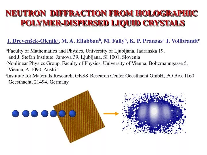
NEUTRON DIFFRACTION FROM HOLOGRAPHIC POLYMER-DISPERSED LIQUID CRYSTALS. I. Dreven š ek-Olenik a , M. A. Ellabban b , M. Fally b , K. P. Pranzas c J. Vollbrandt c a Faculty of Mathematics and Physics, University of Ljubljana, Jadranska 19,

E N D
NEUTRON DIFFRACTION FROM HOLOGRAPHIC POLYMER-DISPERSED LIQUID CRYSTALS I. Drevenšek-Olenika, M. A. Ellabbanb, M. Fallyb, K. P. Pranzasc J. Vollbrandtc aFaculty of Mathematics and Physics, University of Ljubljana, Jadranska 19, and J. Stefan Institute, Jamova 39, Ljubljana, SI 1001, Slovenia bNonlinear Physics Group, Faculty of Physics, University of Vienna, Boltzmanngasse 5, Vienna, A-1090, Austria cInstitute for Materials Research, GKSS-Research Center Geesthacht GmbH, PO Box 1160, Geesthacht, 21494, Germany
NEUTRON PHYSICS WITH PHOTOREFRACTIVE MATERIALS • 1990 - a beam of cold neutrons (0.5 nm < B < 5 nm) was for the first time diffracted from a periodic structure fabricated by optical holographic patterning • (R. A. Rupp et al., Phy. Rev. Lett. 64, 301 (1990)) • Photo-neutron-refractive (PNR) effect = optical illumination-induced modifications of the photosensitive material cause refractive index changes for neutrons. • PNR effect provides: • Structural characterization of holographic media on the nanoscale • Convenient way for fabrication of various neutron-optical devices for cold and ultracold neutrons (beam splitters, mirrors, lenses, interferometers, ...)
NEUTRON OPTICS Coherent elastic scattering of cold neutrons with wavelengths of 0.5 nm < n < 5 nm, can be described rigorously by a one-body, time-independent Schrödinger equation, which can be expressed as: , where the refractive index for neutrons is given as: . Nuclear potential V(x) is usually replaced by a series of Fermi pseudopotentials: , wherebjis the bound coherent scattering length of a nucleus jlocated at the site yj, andb(x) is the so-called coherent scattering length density. Consequently . . By averaging over the “unit cell” of the medium one can take
NEUTRON DIFFRACTION Medium with sinusoidal modification of b. Kg=| Kg|=2/ = grating vector B Bragg angle: Bn=sin-1(n/2)
ANGULAR DEPENDENCE OF DIFFRACTED INTENSITY Diffraction efficiency = Id/Iin: two wave coupling approximation (H. Kogelnik, 1969) Id • = n1nd/(cos) grating strength • = d/ deviation from Bragg angle d B Iin The measured () (rocking curve) is the convolution of (,) with angular and wavelength distributions of the incident neutron beam. (M. Fally, Appl. Phys. B 75, 405-426 (2002))
OUR HPDLC SAMPLES • 1D gratings fabricated from UV curable emulsion: • 55 wt% of the LC mixture (TL203, Merck), • 33 wt% of the prepolymer (PN393, Nematel), • 12 wt% of the 1,1,1,3,3,3,3-Hexafluoroisopropyl acrylate • (HFIPA, Sigma-Aldrich). • I. Drevenšek Olenik, M. E. Sousa, A. K. Fontecchio, G. P. Crawford, M. Čopič:Phys. Rev. E, 69, 051703-1-9 (2004). • Standard glass cells with 50 or 100 m thick spacers, • Exposure: Ar laser, UV = 351 nm, 2 beams with j ~ 10 mW/cm2 • Unslanted transmission grating, = 0.43, 0.56, 1.0, 1.2 m, • Postcuring:Exposure to one beam for ~ 5 min. SEM image of an “opened” sample Diffraction pattern observed for optical beam with O=543 nm at normal incidence.
OPTICAL DIFFRACTION IN THE NEMATIC PHASE I0 I-1 I+1 I-2 I+2 Iin Grating = 1.2 m: Angular dependence of the 1st order diffracted intensities. • Strong difference between • p- and s- polarized beams. • Overmodulated diffraction for p-polarized light.
OPTICAL DIFFRACTION IN THE ISOTROPIC PHASE Grating = 1.2 m = n1opd/(cos), = d/ The fit gives: s =1.89 0.03 , p = 1.840.03 d = 30.50.4 m , n0op= 1.520.01 and n1op= 0.0110.001 Accordingly to the sample composition max possible n1,op=0.038. I. Drevensek-Olenik, M. Fally, M. Ellaban, Phys. Rev. E74, 021707 (2006).
NEUTRON DIFFRACTION EXPERIMENTS • SANS-2 instrument at the Geesthacht Neutron Facility (GeNF) • Beam size: circular spot with 5 mm diameter • Central neutron wavelengths used: n = 1,16 nm; n = 1,96 nm • Wavelength spread: ( n /n)= 10% • Full collimation distance of 40 m was used (angular spread ~0.5 mrad) • Maximum detector distance of 21 m was used. • 2D decetor with 256x256 pixels (2.2 x 2.2 mm2) • All measurements were done at 22oC
NEUTRON DIFFRACTION IN THE NEMATIC PHASE Grating = 1.2 m • Diffraction pattern for n = 1,96 nm • measured at =0o. • The diffraction efficiency of the 1st diffraction orders is around 10% !!! • Diffraction peaks up to the 2nd order are visible. (non-deuterated sample!!)
ANGULAR DEPENDENCE of NEUTRON DIFFRACTION Sample 10g Sample 10f n = 1,16 nm Bn=sin-1(n/2)=0.48 mrad Red line = fit to From the fit it follows: n1n= (2.120.05)10-6, d=30 m => b1=(9.890.26)1012 m-2 The corresponding modulation of the coherent scattering length density b1is two orders of magnitude larger than in the best PNR materials reported up to now!! b1= (bN), due to phase separation of the constituent compounds (b) can be large even if (N) is relatively small !!! M. Fally, I. Drevensek-Olenik, M. Ellaban, K. P. Pranzas, J. Vollbrandt, Phys. Rev. Lett. 97, 167803 (2006).
WHAT ARE THE BENEFITS ? • From the info on chemical composition of our samples we calculated n0 ~ (1–7·10-5). • While we detected n1n~ 6.3 ·10-6(for n = 1.96 nm). • This means that in our HPDLC gratings 10% variation of the V(x) for neutrons was induced by optical holographic patterning. • For observed n1n the value of = 100% can be reached by grating thickness d = 156 m !!! • Low thickness brings important advantages in construction of neutron optical devices: • low level of incoherent scattering (no need for material deuteration = low price) • alignment procedures for different neutron-optical elements become very simple!!
INCREASING GRATING THICKNESS Grating = 1 m, spacers dS = 50 and 100 m cell thickness dS n.d. efficiency grating thickness d ref. ind. modulation n1n (1.16 nm) 50 m 0.9 % 36 4 m1.0 ·10-6 100 m 0.5 % 87 6 m0.3 ·10-6 Increased sample thickness resulted in lower refractive index modulation for neutrons ?!? Besides this an anusual double Bragg peak was observed. • According to two beam coupling theory: • =at=/d=0.01 rad. So we actually see 2 separate Bragg peaks. Possible explanation
DECREASING GRATING PITCH Grating = 0.56m, spacers dS = 50 m (d = 30 5 m). Kogelnik Gaussian Lorentzian n1n~ 1.1 ·10-6(for n = 1.16 nm). Decreasing grating pitch resulted in smearing and broadening of the Bragg peak, which is attributed to structural inhomogeneities.
CONTRAST VERSUS GRATING PITCH Our acrylate-based HPDLC mixture is very convenient for fabricating structures with > 1 m, but less suitable for submicron patterning. n AFM images of polymer matrix = 0.43m 0.56m 1.0m
FUTURE PERSPECTIVES • Probing of other sample compositions (different polymers, LCs, ...) • (Re)filling of the grating structures with high contrast materials (D2O, ...) • Study of photopolymerization kinetics of H-PDLCs by neutron scattering in-situ • Synchronous probing of optical and neutron refractive properties • Investigations of sample morphology on the nanoscale • Investigations of structural modifications induced by external fields • Fabrication of 2D and 3D grating structures for neutrons • Assembling of neutron-optical elements HOLONS-setupat GeNF M. Fally, C. Pruner, R.A. Rupp, G. Krexner, Neutron Physics with Photorefractive Materials in Springer Series of Optical Sciences115, eds. P. Gunter and J.-P. Huignard, Springer Verlag, 2007.
CONCLUSIONS • Photopolymerization-induced phase separation of the constituent components in • H-PDLCs causes a huge variation of refractive index for light as well as for neutrons. • H-PDLC transmission gratings with the thickness of only few tens of micrometers act as extremely efficient gratings for neutrons. • The light induced refractive index-modulation for neutrons in HPDLCs is two orders of magnitude larger than found in the best PNR materials probed up to now. • These features make H-PDLCs very promising candidate for fabrication of neutron-optical devices • Our results also demonstrate that neutron diffraction is a very convenient tool to investigate structural properties of the H-PDLCs. C. Pruner et al., Nuclear Instruments and Methods in Physics Research Section A 560, 598 (2006).
PARTICIPATING RESEARCHERS M. A. Ellabban H. Eckerlebe, M. Fally, M. Bichler I. Drevensek Olenik P. K. Pranzas J. Vollbrandt ____________________________________________________________________________________________ We acknowledge the financial support of ÖAD and Slovenian Research Agency (bilateral projects SI-A4/0708 and SI-AT/07-08-004), the Austrian Science fund FWF (project P-18988), and support of the GKSS–Research Center Geesthacht.