Download
1 / 61
620 likes | 885 Views
Fast Least Squares Migration with a Deblurring Filter. 30 October 2008 Naoshi Aoki. Outlines. Motivation Deblurring filter theory A numerical result of the deblurring filter Deblurred LSM theory Numerical results of the deblurred LSM Conclusions. Outlines. Motivation

E N D
Fast Least SquaresMigrationwith a Deblurring Filter 30 October 2008 Naoshi Aoki
Outlines • Motivation • Deblurring filter theory • A numerical result of the deblurring filter • Deblurred LSM theory • Numerical results of the deblurred LSM • Conclusions
Outlines • Motivation • Deblurring filter theory • A numerical result of the deblurring filter • Deblurred LSM theory • Numerical results of the deblurred LSM • Conclusions
Forward and Inverse Problemsfor Acoustic Wavefield • Forward problem: where d is data, L is forward modeling operator, and m is reflectivity model. • Inverse problem: where LT is an adjoint of forward modeling operator, and [LTL]-1 is the inverse of Hessian.
Alternatives to Direct Inversion • Migration • LSM (e.g., Nemeth, Wu and Schuster,1999) where
The U Model Test 3D U Model Model Description Model size: 1.8 x 1.8 x 1.8 km U shape reflectivity anomaly Cross-spread geometry Source : 16 shots, 100 m int. Receiver : 16 receivers , 100 m int. 0 Data TWT (s) ● Source ● Receiver 5 0 1.8 X (m) U model is designed for testing Prestack 3D LSM with arbitrary 3D survey geometry.
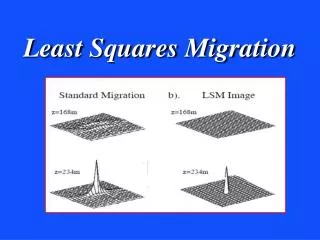
Depth Slices fromMigration and LSM Kirchhoff Migration Images (a) Actual Reflectivity (c) Z = 250 m (e) Z = 750 m (g) Z=1250m LSM Images after 30 Iterations (b) Test geometry (d) Z=250m (f) Z=750m (h) Z=1250m ● Source ● Receiver
Challenges in LSM Processing • Estimation of modeling operators • Velocity Model • Source wavelet • Computational Cost • LSM typically requires 10 or more iterations. • Each LSM iteration requires about 3 times higher computational cost than that of the migration.
Outlines • Motivation • Deblurring filter theory • A numerical result of the deblurring filter • Deblurred LSM theory • Numerical results of the deblurred LSM • Conclusions
An Alternative to LSM • Deblur the migration imagewith a local non-stationary filtering • Migration deconvolution (Hu and Schuster, 2001), • Deconvolution of migration operator by a local non-stationary filter (Etgen, 2002, Guitton 2004), • FFT based approach(e.g., Lecomte(2008); Toxopeus et al, (2008)).
Deblurring Filter Theory The computational cost is about one iteration of LSM • Actual Migration Image: • Compute a reference migration image from a reference model m’: • Find a deblurring operator with a matching filter (He, 2003) : • Apply the operator to the actual migration image
Outlines • Motivation • Deblurring filter theory • A numerical result of the deblurring filter • Deblurred LSM theory • Numerical results of the deblurred LSM • Conclusions
Point Scatterer Model Test Actual Reflectivity Model CSG Example 1.8 ▼▼▼▼▼▼▼▼▼▼▼▼▼ 0 Z (km) TWT (sec) Scatterer: 50 m x 50 m V=1000 m/s 2.5 2.8 2.5 0 1.5 0.5 X (km) X (km) Fdominant = 5 Hz; λ=200 m -0.1 0 0.1
Migration Image Actual Reflectivity Image Migration Image 0 0 Z (km) Z (km) 2.5 2.5 2.5 2.5 0 0 X (km) X (km) The Rayleigh resolution limit = 200 m -0.1 0 0.1
Deblurred Migration Image Actual Reflectivity Image Deblurred Migration Image 0 0 Z (km) Z (km) 2.5 2.5 2.5 2.5 0 0 X (km) X (km) -0.1 0 0.1
LSM Image Actual Reflectivity Image LSM Image after 30 Iterations 0 0 Z (km) Z (km) 2.5 2.5 2.5 2.5 0 0 X (km) X (km) -0.1 0 0.1
Horizontal Image of the Scatterer 0.1 Reflectivity 0 0.5 1.5 X(km)
Migration Deblurring Test Summary • Deblurring filter improves spatial resolution of migration image about double. • The computational cost is about one iteration of LSM. • The deblurred migration image is slightly noisier than that in the LSM image.
Outlines • Motivation • Deblurring filter theory • A numerical results of the deblurring filter • Deblurred LSM theory • Numerical results of the deblurred LSM • Conclusions
Deblurred LSM Theory • DLSM is a fast LSM with a deblurring filter. • 2 types of DLSM algorithms are proposed: 1. Regularized DLSM (or RDLSM) where mapri is a skeletonized version of , and γis a regularization parameter. 2. Preconditioned DLSM (or PDLSM)
Outlines • Motivation • Deblurring filter theory • A numerical results of the deblurring filter • Deblurred LSM theory • Numerical results of the deblurred LSM • Conclusions
Numerical Results • A synthetic data set from the Marmousi2 model. • A 2D marine data set from the Gulf of Mexico.
Marmousi2 ModelGeological Cross Section (Martin et. al., 2006)
Velocity and Density Models P wave Velocity Model Density Model 0 0 Z (km) Z (km) 3 3 0 15 0 15 X (km) X (km) 1.5 4.5 1 2.6 Velocity (km/s) Density (g/cc)
Traveltime Field Computation P wave Velocity Model Traveltime Field Example 0 0 Z (km) Z (km) 3 3 0 15 0 15 X (km) X (km) 1.5 4.5 1 4 Velocity (km/s) Velocity (km/s) (UTAM ray- tracing code written by He, 2002)
Reflectivity Model and Data Source Wavelet Reflectivity Model 0 2000 Amplitude 0 Z (km) -2000 0 300 3 Time (msec) 6 12 X (km) Fdom = 25 Hz -0.2 0 0.2
Reflectivity Model and Data Reflectivity Model Zero-offset Data 0 0 Z (km) TWT (s) 3 3 6 6 12 12 X (km) X (km) -0.2 0 0.2
Migration Image Actual Reflectivity Model Poststack Migration 0 0 Z (km) Z (km) 3 3 6 6 12 12 X (km) X (km) Velocity: 1800-4500 m/s Wavelength : 70 - 180 m CPU time = 10 minutes -0.2 0 0.2 on a dual processor 2.2 GHz
Deblurring Filter with the Exact Model Step1: Compute Matching Operator Actual Migration Image Exact Model 0 0 f Z (km) Z (km) 3 3 6 6 12 12 X (km) X (km)
Deblurring Filter with the Exact Model Step2: Apply the Operator Deblurred Migration Image Actual Migration Image 0 0 f Z (km) Z (km) 3 3 6 6 12 12 X (km) X (km)
DLSM Convergence Curves RDLSM PDLSM 1 1 Residual Residual 19 8 0 0 1 1 30 30 Iteration Number Iteration Number Damping parameter: Γ= 200000x0.5n-1, n=1,2,…,30
DLSM Images with the Exact Model RDLSM after 19 Iterations PDLSM after 8 Iterations 0 0 Z (km) Z (km) 3 3 6 6 12 12 X (km) X (km)
Model Sensitivity Test • Exact model: • the actual model • Geological model: • Skeletonized Migrated Image • Grid model: • The region is divided into sections; each section has a point scatterer in the center. Geological Model Exact Model Zoom View of Grid Model 0 0 1 Z (km) Z (km) Z (km) 250 x 250 m 3 3 2 10 11 6 6 12 12 X (km) X (km) X (km)
Deblurring Filter with the Geological Model Step1: Compute Matching Operator Reference Migration Image Geological Model 0 0 f Z (km) Z (km) 3 3 6 6 12 12 X (km) X (km)
Deblurring Filter with the Geological Model Step2: Apply the Operator Deblurred Migration Image Actual Migration Image 0 0 f Z (km) Z (km) 3 3 6 6 12 12 X (km) X (km)
DLSM Convergence Curves Regularized DLSM Preconditioned DLSM 1 1 Residual Residual 20 12 0 0 1 1 30 30 Iteration Number Iteration Number Damping parameter: Γ= 200000x0.5n-1, n=1,2,…,30
DLSM Images with the Geological Model RDLSM after 20 Iterations PDLSM after 12 Iterations 0 0 Z (km) Z (km) 3 3 6 6 12 12 X (km) X (km)
Deblurring Filter with the Grid Model Step1: Compute Matching Operator Zoom View of Grid Model Reference Migration Image 0 1 f Z (km) Z (km) 3 2 10 11 6 12 X (km) X (km)
Deblurring Filter with the Grid Model Step2: Apply the Operator Deblurred Migration Image Actual Migration Image 0 0 f Z (km) Z (km) 3 3 6 6 12 12 X (km) X (km)
DLSM Convergence Curves Regularized DLSM Preconditioned DLSM 1 1 Residual Residual 20 10 0 0 1 1 30 30 Iteration Number Iteration Number Damping parameter: Γ= 200000x0.5n-1, n=1,2,…,30
DLSM Images with the Grid Model RDLSM after 20 Iterations PDLSM after 10 Iterations 0 0 Z (km) Z (km) 3 3 6 6 12 12 X (km) X (km)
Marmousi2 Test Summary (1) • The deblurring filter can expedite the computation of an LSM image. • RDLSM and PDLSM provide acceptable LSM images with about 2/3 and 1/3 the cost of standard LSM, respectively. • Controlling the model dependency is required. • RDLSM can control the model dependency with a regularization parameter. • In the PDLSM algorithm, not using a deblurring filter after several iteration is recommended.
Marmousi2 Test Summary (2) • DLSM with the geological model • Computation of an LSM image can be expedited by a human interpretation. • A risk is an erroneous interpretation. The model dependency should be carefully controlled. • DLSM with the grid model • The result is not good as that from a better geological model. • An advantage is that no expense of a human interpretation is required for the model building.
The Gulf of Mexico Data Test 2D Poststack Marine Data 0 TWT(s) 4 8 18 X (km)
The Gulf of Mexico Data Test • Both the regularization and preconditioningschemes are employed in the DLSM. • A geological model is created by the following way: • A deblurred migration image is obtained with a grid model. • A geological model is created by cosmetic filtering and skeletonizing the deblurred migration image.
Zero-offset Data from for a Grid Model 0 TWT(s) Scatterer Interval: 500 m x 500 m 4 8 18 X (km)
Zoom View of Reference Migration Image for a Grid Model 0.4 Z (km) 1.2 10.5 8 13 X (km)
Kirchhoff Migration 0.5 Z (km) 1 1.5 10.5 8 13 X (km)
Deblurred Migration Image 0.5 Z (km) 1 1.5 10.5 8 13 X (km)
Geological Model Reflectivity 0.1 0.5 Z (km) 0 1 1.5 -0.1 10.5 8 13 X (km)